Contactless detection cell with reduced detection channel cross-section

a detection cell and cross-section technology, applied in resistance/reactance/impedence, instruments, material analysis, etc., can solve problems such as affecting the quality of obtained results or spectra, and achieve the effect of increasing the sensitivity of a contactless detection cell

Inactive Publication Date: 2009-08-13
AGILENT TECH INC
View PDF3 Cites 19 Cited by
  • Summary
  • Abstract
  • Description
  • Claims
  • Application Information

AI Technical Summary

Benefits of technology

[0008]By choosing the inner cross-section of at least a part of the detection channel independently of the preceding flow path's cross section, an additional degree of freedom is gained. This additional degree of freedom can e.g. be used for improving any property of the detection cell, for example for at least one of: increasing the separation power, improving the signal-to-noise ratio, reducing cross talk, etc. Besides that, this additional degree of freedom might as well be used for modifying any other property of the detection cell that has not been mentioned yet, in order to improve the detection cell's properties in a given context.
[0009]According to a preferred embodiment of the invention, the resistance of the sample volume in the detection channel is increased by lowering the inner cross section of the detection flow path between the transmitter electrode and the receiver electrode. By narrowing the detection channel, the sample volume is stretched and spread out, and its resistance is increased. As a consequence, variations in resistance caused by the various sample compounds are enhanced and can be monitored more precisely. The signal-to-noise level is increased, and the detection cell's sensitivity is improved. Furthermore, by narrowing the detection channel, the analyte's resistance becomes the most significant contribution to the overall impedance measured between the electrodes.
[0011]According to a preferred embodiment, the transmitter electrode and the receiver electrode are separated by a distance that is sufficiently large for reducing or even avoiding distortions related to cross-talk. On the one hand, by increasing the distance between the electrodes, the amount of cross-talk can be reduced. On the other hand, by increasing the distance between the electrodes, the detection cell's volume might be increased as well, and as a consequence, the resolution of the obtained measurements might be lowered. However, by reducing the inner cross section, the detection cell volume can be kept small without bringing the electrodes too close together. Hence, it is possible to provide a detection cell with a small detection cell volume and with electrodes that are axially spaced apart by a rather large distance. As a result, the detection cell has low susceptibility to cross talk and yields high-resolution measurements.
[0013]According to an alternative embodiment, the inner cross-section of the detection channel is axially varied in a way that, at the locations of the electrodes, its inner diameter is large, whereas between the electrodes, its inner cross-section is small. Thus, an hour-glass shaped detection channel is obtained. This geometry might also be referred to as an “inverted bubble”. By increasing the inner diameter at the sites where the ring-shaped electrodes are located, the capacitive coupling between the transmitter electrode and the sample is improved, and the capacitive coupling between the receiver electrode and the sample is imp roved as well. Together with the sample, the respective electrode represents a capacitance. By increasing the inner diameter of the detection channel at the locations of the electrodes, the effective “surface” of the respective capacitance is increased, while the distance between the sample an d the electrode is decreased. As a result, the respective capacitances are increased. Due to the improved capacitive coupling, the resistance of the sample between the electrodes can be measured more accurately, because it provides the major contribution to the total (complex) impedance between the electrodes.
[0016]According to an alternative embodiment of the invention, the detection channel shape is implemented using microstructuring technologies as common for making microfluidic chip devices. Such microstructuring technologies might e.g. include etching, laser ablation, direct molding. Using these techniques, the detection channel can be shaped with high precision. Microsystem technologies allow for an accurate positioning of contactless electrodes relative to the detection volume. In yet another preferred embodiment, the detection channel is implemented as a part of a microfluidic chip device.
[0024]Furthermore, embodiments of the present invention relate to a method for increasing the sensitivity of a contactless detection cell, with said detection cell being adapted for detecting an electrical property of one or more sample compounds. The detection cell comprises a transmitter electrode adapted for capacitively coupling an AC signal into a detection channel and a receiver electrode adapted for receiving an AC response signal in response to the AC signal that has been coupled into the detection channel. The method comprises a step of reducing, in at least a section of the detection channel, the inner cross-section of the detection channel relative to the inner cross-section of the flow path towards the detection channel.

Problems solved by technology

A further aspect is cross-talk between the transmitter electrode and the receiver electrode, which impairs the quality of the obtained results or spectra.

Method used


Image

  • Contactless detection cell with reduced detection channel cross-section
  • Contactless detection cell with reduced detection channel cross-section
  • Contactless detection cell with reduced detection channel cross-section

Examples


Embodiment Construction

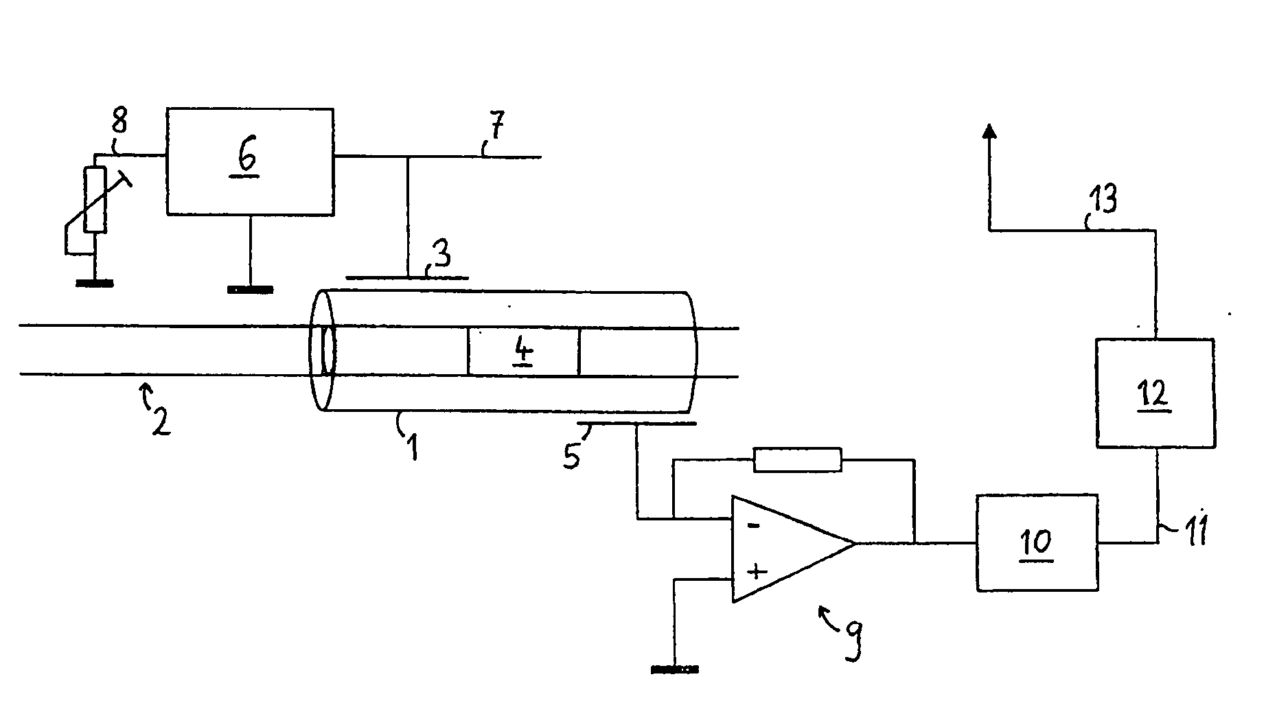
[0031]In FIG. 1, a measurement set-up comprising a contactless detection cell is depicted. The contactless detection cell 1 is adapted for detecting compounds that have migrated through a preceding separation flow path 2, whereby the separation flow path 2 might e.g. be part of a capillary electrophoresis (CE) system, or of a liquid chromatography (LC) system, etc. The contactless detection cell 1 comprises a transmitter electrode 3 that is adapted for applying an AC field to the detection volume 4, and a receiver electrode 5 that is adapted for detecting the AC current that passes through the detection volume 4. The transmitter electrode 3 and the receiver electrode 5 are arranged in an axial geometry, which means that they are spaced apart by a certain distance in the direction of the flow. The transmitter electrode 3 is connected to a high frequency (HF) AC power supply 6 that provides a HF AC voltage signal 7 to the transmitter electrode 3, whereby the frequency of the HF AC vol...


PUM

PropertyMeasurementUnit
inner diameteraaaaaaaaaa
frequencyaaaaaaaaaa

Abstract

A contactless detection cell (1) for detecting an electrical property of one or more sample compounds in a flow path is described. The contactless detection cell (1) comprises a transmitter electrode (3) adapted for capacitively coupling an AC current into a detection channel (4) of the flow path, and a receiver electrode (5) adapted for receiving the AC current that has been coupled into the detection channel (4). An inner cross-section (IDDET) in at least a section of the detection channel is different than an inner cross-section (IDSEP) of the flow path (2) towards the detection channel (4).

Description

BACKGROUND OF THE INVENTION[0001]The present invention relates to a contactless detection cell for detecting an electrical property of one or more sample compounds in a flow path, to a separation system comprising a contactless detection cell, and to a method for increasing the sensitivity of a contactless detection cell.[0002]Contactless detection of an electrical property of sample compounds has become an important alternative to optical detection techniques. For example, in the field of analyzing ions in liquid samples, contactless conductivity detection (CCD) has become a competitive technique. The present invention can be applied to contactless detection of any electrical property.SUMMARY OF THE INVENTION[0003]It is an object of the invention to provide an improved contactless detection of an electrical property of one or more sample compounds in a flow path. The object is solved by the independent claims. Preferred embodiments are shown by the dependent claims.[0004]According ...

Claims


Application Information

Patent Timeline
Patent Type & Authority Applications(United States)
IPC IPC(8): G01R27/08G01N30/64G01N27/08G01N27/447G01N30/60
CPCG01N27/08G01N30/64G01N30/6095G01N27/4473
Inventor KALTENBACH, PATRICKWITT, KLAUSGAS, BOHUSLAVVAN DE GOOR, TOM
Owner AGILENT TECH INC
Why Eureka
Try Eureka