
Miniature Physiological Telemeter

a physiological telemeter and miniature technology, applied in the field of miniature physiological telemeters, can solve the problems of sufficiently small devices and lightweight devices to remain in place while being used, and achieve the effects of saving power, saving circuit complexity, and usefully reducing the separation distance of probes

Inactive Publication Date: 2009-08-13
INNERSEA TECH
View PDF6 Cites 31 Cited by
  • Summary
  • Abstract
  • Description
  • Claims
  • Application Information

AI Technical Summary

Benefits of technology

"The invention is a wireless, unobtrusive, multi-sensory instrumentation system that can be used on subjects engaged in physical activities. The system includes small, self-contained sensors that can be attached to the skin or inside of an animal or human. The sensors are designed to transmit high-quality, multi-variable physiological data to a receiver, which can analyze the data using existing commercial or laboratory software. The system is easy to use, portable, and can be used in a variety of medical applications. The overall size and weight of the system is minimized to prevent skin irritation or ulceration. The system uses asynchronous pulse position modulation to dissipate power and minimize signal conditioning. The use of multiple physiological telemeters allows for simultaneous monitoring of multiple variables. The system can be used in long-term monitoring applications and is adaptable to different physical activities and sports. The overall circuit concept is designed to minimize power requirements and can be used in a variety of medical applications."

Problems solved by technology

These devices are sufficiently small and lightweight to remain in place while transmitting reliable data, even during movements involving high accelerations.

Method used


Image

  • Miniature Physiological Telemeter
  • Miniature Physiological Telemeter
  • Miniature Physiological Telemeter

Examples


example i

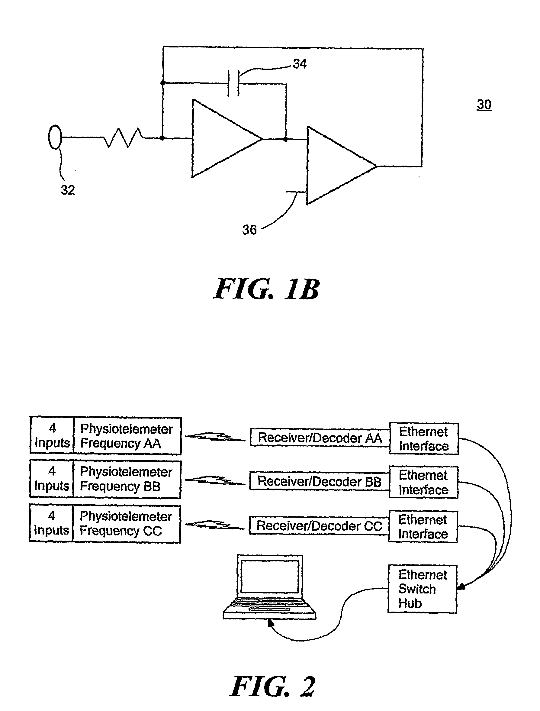
Receiver / Decoder Units that Send Data to an Ethernet Capable Computer

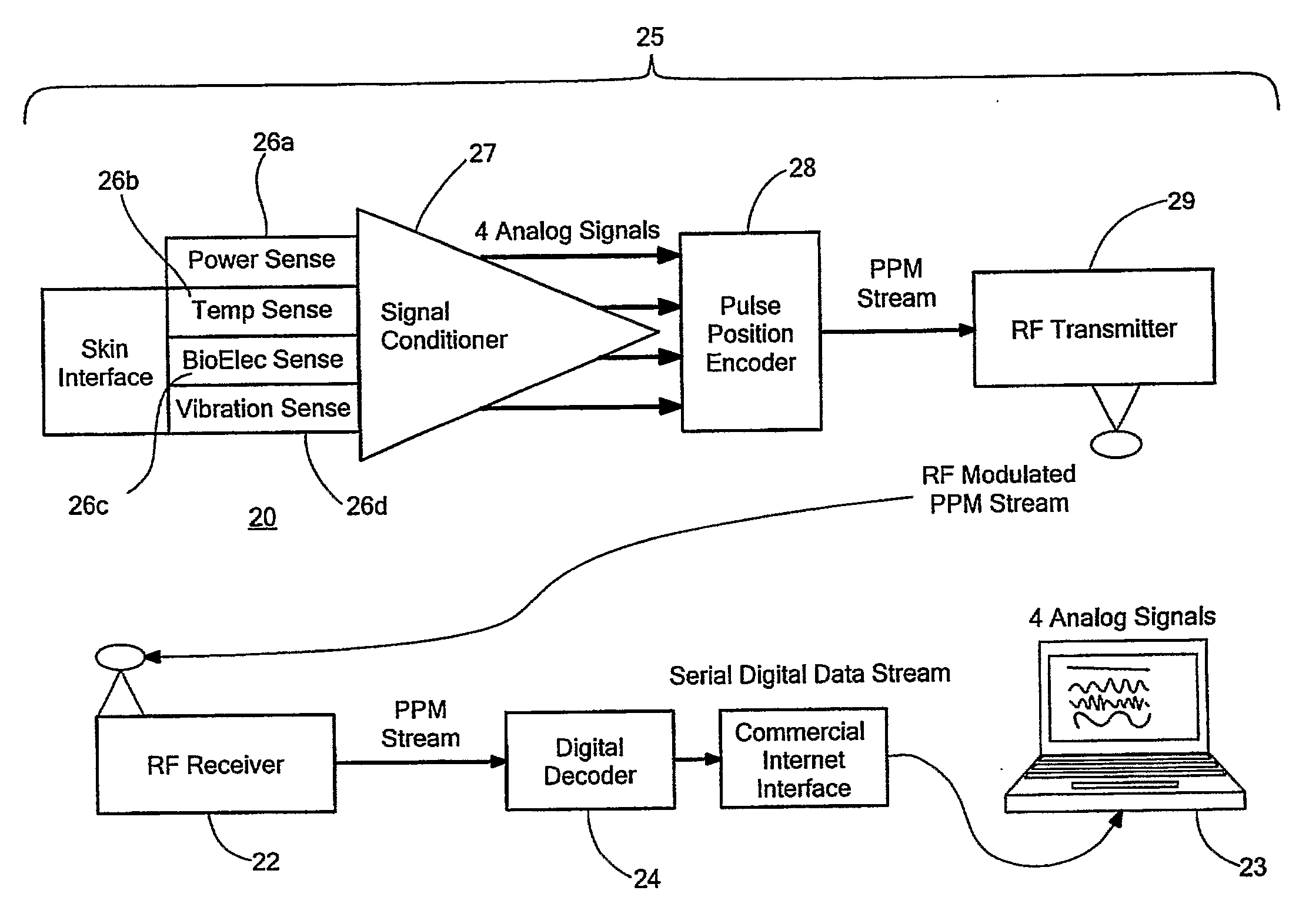
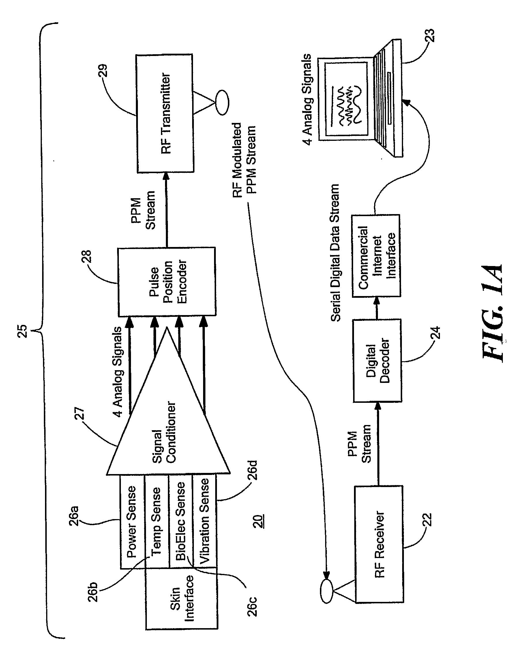
[0091]Referring again to FIG. 1A, the front end of an RF receiver circuit 22 is a commercially available IC designed to operate in a 315-450 MHz band. A signal strength indicator pin (not shown) conveniently reflects the incoming power at the center frequency, so all of the RF-to-pulse translation is accomplished in this single integrated circuit (IC). The resulting waveform contains all signal pulse energy, as well as noise from other sources and is applied to an adaptive threshold detector (not shown). The adaptive threshold detector first senses the noise floor using an RMS circuit. This is equivalent to the standard deviation of the incoming signal. Then, based on an adjustable multiplier, the threshold is set. Since they are very short, the incoming pulses mixed with noise do not significantly impact the computation of the threshold. The multiplier is chosen based on the desired statistics of the detection pro...

example ii

Battery Powered 4-Sensor Physiological telemeter that Operates on Three Unique RF Frequencies using Surface Mount Technology

[0093]Several approaches can be taken to reduce power requirements. One design approach is to minimize component count and use commercial rail-rail low power IC op amps, which consume less than 70 μA / OpAmp at 2 volts. Reducing the size of the circuit enhances performance, as parasitic capacitances and inductances are minimized by shorter traces.

[0094]For clinical rehabilitation, post-surgical recovery, and sports medicine applications, any device worn on the skin should be extremely small and lightweight. In order to construct an unobtrusive wearable telemeter, power consumption (hence battery and final package size and mass) should be minimized. One embodiment incorporates only essential functions into the telemeters. For example, the telemeters can function as much as possible as simple data acquisition and encoding modules with minimal signal conditioning, u...

example iii

Hollow Glass Spherical Filler for Packaging

[0099]Hollow glass spheres of about 100 mu. in diameter, such as those available from 3M under the trade name Scotchlite Glass Bubbles K Series and S Series, are mixed with silicone to create an encapsulation material. The hollow glass spheres are preferably packed tightly, such as by a centrifuge. Essentially, the silicon acts as an adhesive to adhere the spheres to each other. The resulting encapsulation material is quite rigid. The hollow glass spheres reduce the stretchiness, weight, density, thermal conductivity, stray capacitance and dielectric constant of the encapsulation material.

[0100]Referring to FIG. 6, the resulting encapsulation material is used to encapsulate electronic circuitry of a surface-mounted, multichannel telemeter, biometric sensors, electric wires interconnecting the biometric sensors and the telemeter and / or other components. Optionally, these elements and the encapsulation material can be further encapsulated in ...


PUM


Abstract

A low power miniaturized telemeter (25, 40-42) provides data from a monitored subject at internal or external locations. A charge integration and pulse stream encoding (30) in the telemeter (25, 40-42) contributes to reduced power consumption. A transmitter (29) in the telemeter (25, 40-42) may be omnidirectional to permit operation without physical obstruction or limitations to movement. A receiver (22) collects transmitted information and may have an adaptive threshold pulse detector to permit further reductions in power usage. The telemeter (25, 40-42) can multiplex monitored parameters on a time division basis to permit trans-mission of multiple data channels. Individual telemeters may have unique transmission frequencies to permit multiple telemeters to be used concurrently without interference. A self-contained power source in the telemeter (25, 40-42) permits long term operation at low power without the need of replacement. The telemeter (25, 40-42) can be packaged to accommodate a number of applications, such as by permitting adjustable density.

Description

CROSS REFERENCE TO RELATED APPLICATIONS[0001]This application claims the priority of U.S. Provisional Application Nos. 60 / 681,520 filed May 16, 2005 and 60 / 681,887 filed on May 17, 2005 both of which were entitled MINIATURE PHYSIOLOGICAL TELEMETER, the whole of which is hereby incorporated by reference herein.STATEMENT REGARDING FEDERALLY SPONSORED RESEARCH OR DEVELOPMENT[0002]N / ABACKGROUND OF THE INVENTION[0003]While advanced instrumentation is readily available for physiological monitoring and research, this instrumentation is generally not portable and it must be connected to a patient or subject with wire leads. For many studies with sedentary subjects, direct lead recordings are acceptable. However, when it is desirable to have patients or subjects exercise while being monitored, wired attachments are problematic, because wiring can dislodge sensors or cause artifacts in recordings. If a large number of monitoring points are of interest during physical activities, particularly ...

Claims


Application Information

Patent Timeline
Patent Type & Authority Applications(United States)
IPC IPC(8): G08C19/00A61B5/00
CPCA61B5/0002A61B2562/02A61B2560/0209A61B5/0488A61B5/389
Inventor EDELL, DAVID J.
Owner INNERSEA TECH
Learn More