Pickup device

a pickup device and optical technology, applied in the field of optical pickup devices, can solve the problems of noise, leakage of signal from lb>1/b>, and deterioration of the quality of the output signal of the photo detector

Inactive Publication Date: 2009-08-13
PIONEER CORP
View PDF9 Cites 21 Cited by
  • Summary
  • Abstract
  • Description
  • Claims
  • Application Information

AI Technical Summary

Benefits of technology

[0012]In the conventional art, the overlap between the signal light and the stray light in the photo detector is prevented using a light shading band or a hologram. In the conventional art, however, some of the signal light necessary for the reproduction is shaded, with the result that the quality of the signal reproduced is deteriorated. Also, the partition number of the photo detector increases, although the light shading region is received by the photo detector, and the number of adders to acquire a desired signal from the output signal of the photo detector increases, with the result that operational noise increases.

Problems solved by technology

As a result, a signal from L1 leaks to some extent.
The stray light except the signal light interferes with the signal light, with the result that noise may occur.
Also, the quality of an output signal from the photo detector may be deteriorated, and defects, such as the offset of a servo error signal, may occur.

Method used


Image

  • Pickup device
  • Pickup device
  • Pickup device

Examples


first embodiment

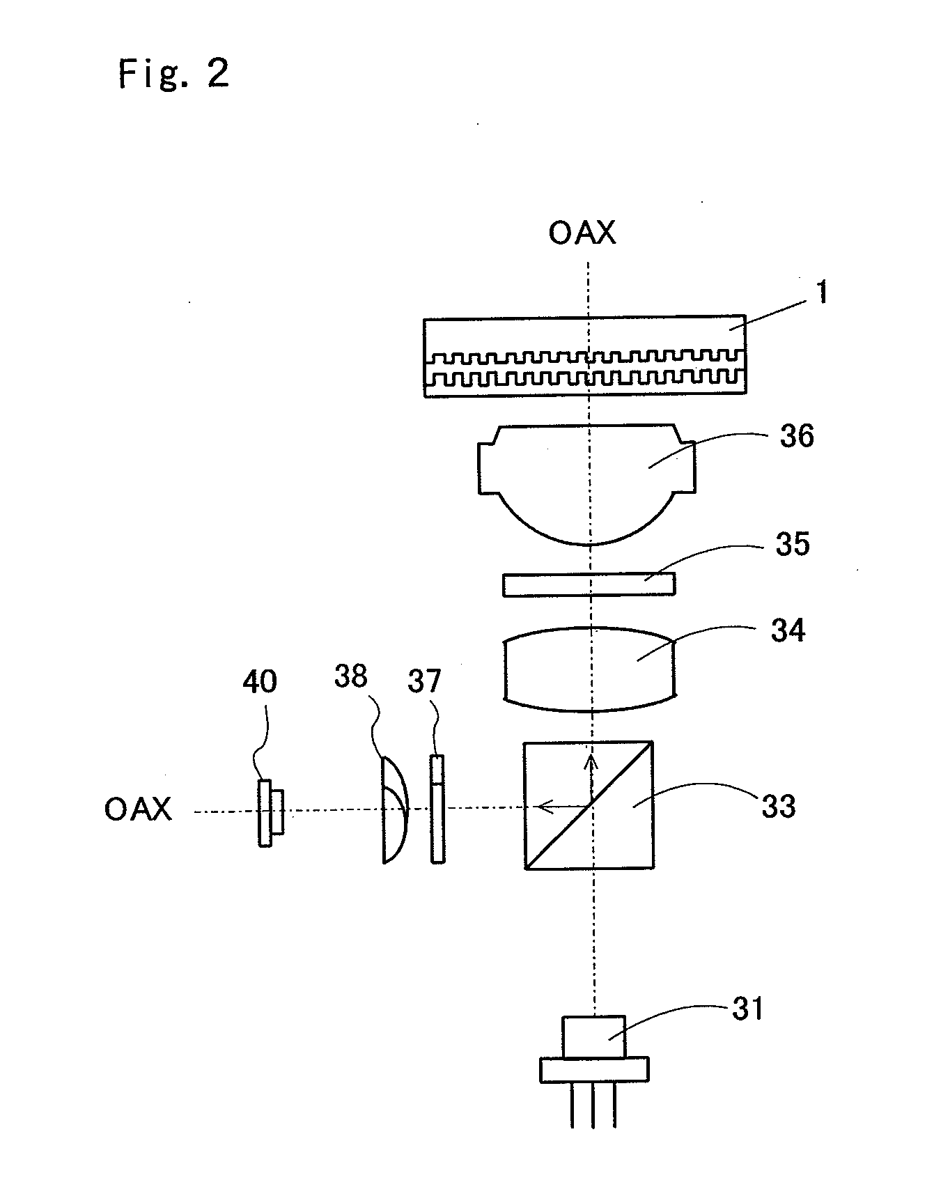
[0085]FIG. 2 is a schematic view illustrating the structure of an optical pickup device 3 according to a first embodiment of the present invention. The optical pickup device 3 includes a semiconductor laser 31 as a light source, a polarization beam splitter 33, a collimator lens 34 to convert divergent light into parallel light, a quarter wave plate 35, an object lens 36, a divisional wave plate device 37, an astigmatic device 38, and a photo detector 40 to perform photoelectric conversion.

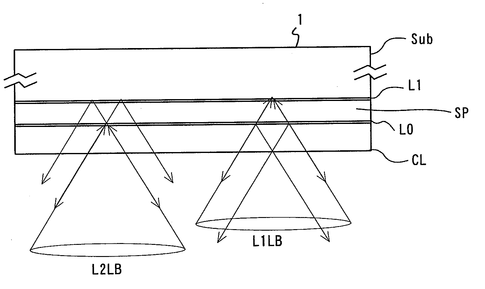
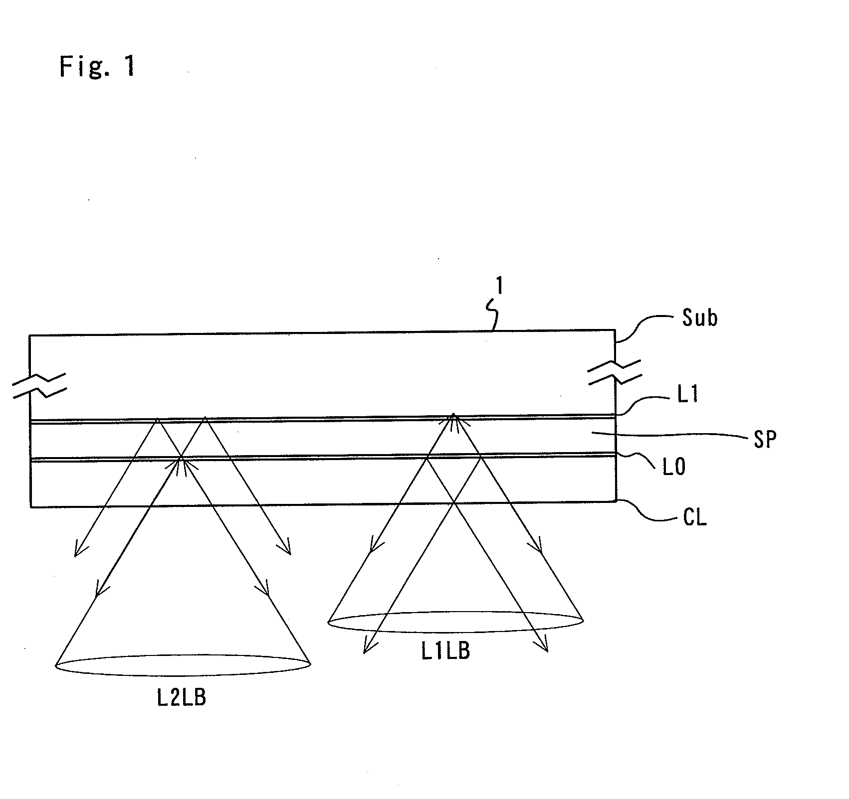
[0086]An optical disk 1 is an optical recording media having a plurality of recording layer stacked while a spacer layer is interposed between the recording layers. The optical disk 1 is placed on a turntable (not shown) of a spindle motor such that the optical disk 1 is spaced apart from the object lens 36.

[0087]The object lens 36, for focusing light flux on a target recording surface of the optical disk 1 to form a spot, is included in an irradiation optical system. The object lens 36 is movably...

second embodiment

[0103]FIG. 11 is a schematic perspective view illustrating the structure of the principal part of an optical pickup device according to a second embodiment of the present invention.

[0104]The optical pickup device 3 includes a semiconductor laser 31 as alight source, a sub beam creating diffraction grating 32, a polarization beam splitter 33, a collimator lens 34, a quarter wave plate 35, a start-up mirror M, an object lens 36, a divisional wave plate device 37, an astigmatic device 38 which is a transmissive hologram device, and an photo detector 40. An optical disk 1 is placed on a turntable (not shown) of a spindle motor at the center CODK thereof such that the optical disk 1 is spaced apart from the object lens 36 in the direction perpendicular to the disk surface (the optical axis direction). Also, the divisional wave plate device 37 of FIG. 11 is formed to correspond to the edge of the polarization beam splitter 33. However, only the external appearance of the divisional wave p...

third embodiment

[0116]FIG. 14 illustrates a photo detector 40 of a pickup device according to a third embodiment of the present invention, which is identical in construction to that of the second embodiment except the change in shape of the light receiving parts of the sub optical detection units 401 and 402. The photo detector 40 is constructed such that a large number of tracking error signals (push pull signals) can be detected by the light receiving parts of the sub optical detection units 401 and 402.

[0117]As shown in FIGS. 14 and 15, the shape of the light receiving parts of the sub optical detection units 401 and 402 is configured such that the light receiving parts are spread in the shape of a fan, i.e., the light receiving parts protrude toward the divisional regions 401a and 402a at the division lines 37M and 37L of the divisional wave plate device 37 of the division device and outlines CTL approximately coinciding with the intersection point between the division lines 37M and 37L (in the...


PUM

PropertyMeasurementUnit
angleaaaaaaaaaa
angleaaaaaaaaaa
angleaaaaaaaaaa

Abstract

A pickup device includes an irradiation optical system including an object lens for focusing light flux on a track of a recording surface of an optical recording media having a plurality of recording layers stacked while a spacer layer is interposed between the recording layers to form a spot and a detection optical system including an photo detector having a plurality of light receiving parts for receiving returning light reflected from the spot through the object lens to perform photoelectric conversion. The pickup device controls a position of the object leans according to an electrical signal calculated from outputs of the light receiving parts. The pickup device further includes an astigmatic device for providing astigmatism to the returning light directed to the light receiving parts and a division device, having divisional regions divided by a division line extending in an astigmatic direction about an optical axis of the returning light, for dividing the returning light having the astigmatism into a plurality of partial light fluxes divided for the respective divisional regions along the optical axis of returning light. The neighboring divisional regions provide the partial light fluxes with an optical action so that interference between the corresponding partial light fluxes does not occur on the light receiving parts.

Description

BACKGROUND OF THE INVENTION[0001]1. Field of the Invention[0002]The present invention relates to an optical pickup device used in a recording and reproducing apparatus for an optical recording medium, such as an optical disk, etc., and more particularly to an optical pickup device that is capable of controlling the optimum focusing position of light flux focused on a target recording surface of an optical recording medium, such as an optical disk, etc., having a plurality of recording layers stacked using an astigmatic method.[0003]2. Description of the Related Art[0004]In recent years, an optical disk has been widely used as a means to record and reproduce various kinds of data, such as video data, audio data, computer data, etc. A high-density recording type disk called a Blu-ray™ Disk (hereinafter, referred to as a BD) has been put to practical use. This optical disk standard encompasses a multi-layer optical disk in which a plurality of recording layers are laminated. In a multi...

Claims


Application Information

Patent Timeline
Patent Type & Authority Applications(United States)
IPC IPC(8): G11B7/00G11B7/13G11B7/135
CPCG11B7/0909G11B7/131G11B2007/0013G11B7/1353G11B7/1378G11B7/133
Inventor OGASAWARA, MASAKAZUYANAGISAWA, TAKUMAKOIKE, KATSUHIRO
Owner PIONEER CORP
Why Eureka
Try Eureka