Supercharge Your Innovation With Domain-Expert AI Agents!

GPS enabled epirb with integrated receiver

a receiver and gps technology, applied in the field of emergency position indicating radio beacons, can solve the problems of affecting affecting the user experience, and not revealing or teaching the existence of the epirb, so as to improve the effectiveness of the sensor

Active Publication Date: 2009-08-20
ACR ELECTRONICS INC
View PDF9 Cites 24 Cited by
  • Summary
  • Abstract
  • Description
  • Claims
  • Application Information

AI Technical Summary

Benefits of technology

[0013]The integrated GPS receiver system includes both internal GPS global positioning system and external GPS sources The EPIRB's external GPS interface is an infrared (“IR”) interface that includes an Automatic Background Light Adjustment algorithm for adjusting the IR sensor light level as a function of the background light conditions in order to improve the sensor's effectiveness.
[0016]It is another object of the invention to provide an EPIRB that includes a GPS source switch that allows the EPIRB to receive GPS inputs from an internal source and an external source, or both. The external source interface is an IR sensor that includes an Automatic Background Light Adjustment algorithm for adjusting the IR sensor light level as a function of the background light conditions in order to improve the sensor's effectiveness.

Problems solved by technology

Furthermore, many times these EPIRBs get activated far out to sea, where no other means of communications are feasible.
Another limitation of the present-day EPIRB is its user interface.
This pending patent application does not disclose or teach having an EPIRB that itself includes a display screen and a transmitter for transmitting text messages from the user.
A limitation of this EPIRB using an IR interface to input external GPS coordinates is the degraded performance due to the wide range of required operating background lighting conditions, from bright sunlight to pitch black at nighttime.

Method used


Image

  • GPS enabled epirb with integrated receiver
  • GPS enabled epirb with integrated receiver
  • GPS enabled epirb with integrated receiver

Examples


Embodiment Construction

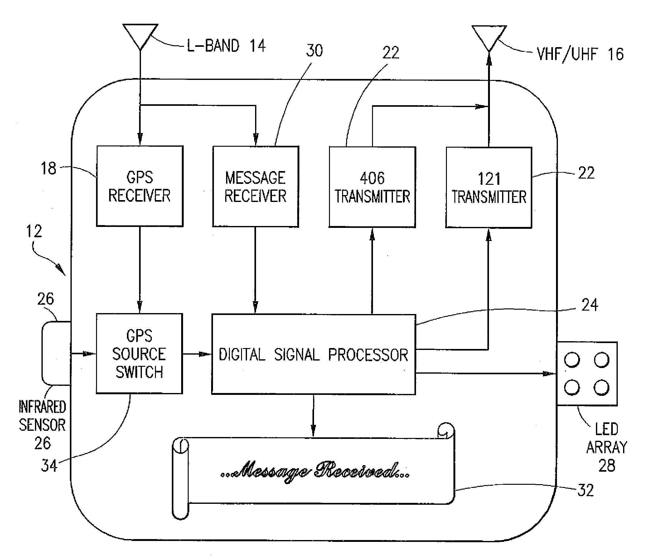
[0025]Referring now to FIG. 1, a block diagram of the present invention is generally shown in (12), comprised of an L-Band antenna (14) for receiving GPS signals along with a GPS receiver (18) for processing the signal, a VHF / UHF antenna (16) along with a 121.5 MHz transmitter (22) and a 406 MHz transmitter (20) used for sending emergency distress signals, and a Digital Signal Processor (24) used to process all the signals and control the EPIRB. The present invention also includes the addition of a message receiver (30), a graphical display device (32), a GPS source switch (34) used to select between internally generated coordinates coming from the GPS receiver (18) or externally supplied coordinates coming in from an infrared sensor (26), and a LED array (28) used to create a visible flashing strobe.

[0026]The message receiver (30) in the preferred embodiment of the present invention is designed to receive SATCOM signals in the L-Band, thereby reusing the existing L-band antenna (14...


PUM


Abstract

An Emergency Position Indicating Radio Beacon (EPIRB) comprising an integrated wireless receiver, a graphical display device, capability to utilize both internal and external GPS coordinate sources, an infrared background lighting adjustment algorithm, and a multi-LED strobe light array. The receiver provides a return communications path back to the beacon, which is used to acknowledge the receipt of the beacon's outgoing emergency signal by Search and Rescue satellites. The display is used to visually display various operational status information as well as any received messages coming back into the receiver. The GPS receiver system switches between internally derived and / or externally supplied GPS coordinates. The present invention also incorporates an Automatic Background Light Adjustment (ABLA) algorithm to compensate for the maximum range of light intensity encountered by infrared communications LEDs during daytime and nighttime operation. Additionally, a multi-LED array is used to flash a signaling strobe in a universal hemispherical pattern.

Description

BACKGROUND OF THE INVENTION[0001]1. Field of the Invention[0002]This invention relates to Emergency Position Indicating Radio Beacons (EPIRBs) that are used to send an emergency signal in the case where a ship or vessel is in trouble and is in need of assistance. In particular, it relates to an EPIRB that utilizes the Global Positioning System (GPS) and sends the EPIRB latitude and longitude coordinates in emergency transmissions at 406 MHz.[0003]2. Description of Related Art[0004]The use of EPIRBs for emergency signaling by vessels in distress is well known in the marine industry. Typically an EPIRB is a RF transmitter that emits signals on one or more frequencies, normally an emergency band frequency, to notify satellites, surrounding ships, and aircraft in the area that a vessel is in trouble. EPIRBs can be either manually activated or automatically activated by contact with ocean or fresh water. Also known is the use of a GPS receiver that can provide very accurate latitude and ...

Claims


Application Information

Patent Timeline
Patent Type & Authority Applications(United States)
IPC IPC(8): H04M11/04
CPCB63B49/00G01S1/68G08B25/016G01S19/17G01S5/0027
Inventor GREER, KERRY L.TONG, CHUNG T.WU, KAIYUCASSINA, CLAUDIOJARUSZEWSKI, FRANCIS M.JACKSON-POWNALL, ANTHONY
Owner ACR ELECTRONICS INC
Features
  • R&D
  • Intellectual Property
  • Life Sciences
  • Materials
  • Tech Scout
  • Unparalleled Data Quality
  • Higher Quality Content
  • 60% Fewer Hallucinations
Learn More