Methods and Apparatus for Monitoring Deposit Formation in Gas Systems

a gas system and deposit technology, applied in the direction of instruments, weighing by removing components, material moisture content, etc., can solve the problems of clogging of instruments and valves, affecting the efficiency of compressors, and affecting the operation of compressors

Active Publication Date: 2009-08-27
BAKER HUGHES INC
View PDF16 Cites 19 Cited by
  • Summary
  • Abstract
  • Description
  • Claims
  • Application Information

AI Technical Summary

Benefits of technology

[0009]There is provided, in one non-limiting form, a method of measuring solids deposits, such as black powder, in a gas environment, such as a high pressure gas test chamber, a gas transmission line or pipeline. The method involves initially measuring the weight gain due to water condensation on a metal-coated quartz crystal microbalance (QCM) in a QCM probe within a high pressure gas chamber of the gas environment. The QCM probe is cooled during the condensation period at constant ΔT (constant condensation rate) or at a controlled ΔT (constant condensation layer) (ΔT=f(t)).
[0010]As the probe is cooled, the rate of change of weight is associated with both the condensation rate and the metal oxidation rate. Subsequently, the probe is heated to the temperature of the gas during the evaporation period of the condensation evaporation (CE) cycle. The final solids deposits weight gain is determined during each CE cycle. The solids deposits weight gain of the metal-coated QCM is continuously measured during at least one subsequent CE cycle, but in most cases during multiple CE cycles. A cumulative solids deposits rate is determined. The weight measurements are conducted at temperature differentials (ΔT) between the high pressure gas c

Problems solved by technology

“Black powder” formation in gas transmission lines, such as sales gas lines, is a problem that has had a serious impact on pipeline operations including, but not necessarily limited to, erosion failures of valves, lower efficiency of compressors, clogging of instrumentation and valves, and problems with Health, Safety & Environment (HS&E) compliance.
Despite the fact that this has been a persistent problem in the industry, there has been little work towards ascertaining the composition, sources and formation mechanism of black powder in gas transmission lines.
Operators report that when black powder moves, i

Method used


Image

  • Methods and Apparatus for Monitoring Deposit Formation in Gas Systems
  • Methods and Apparatus for Monitoring Deposit Formation in Gas Systems
  • Methods and Apparatus for Monitoring Deposit Formation in Gas Systems

Examples


example 1

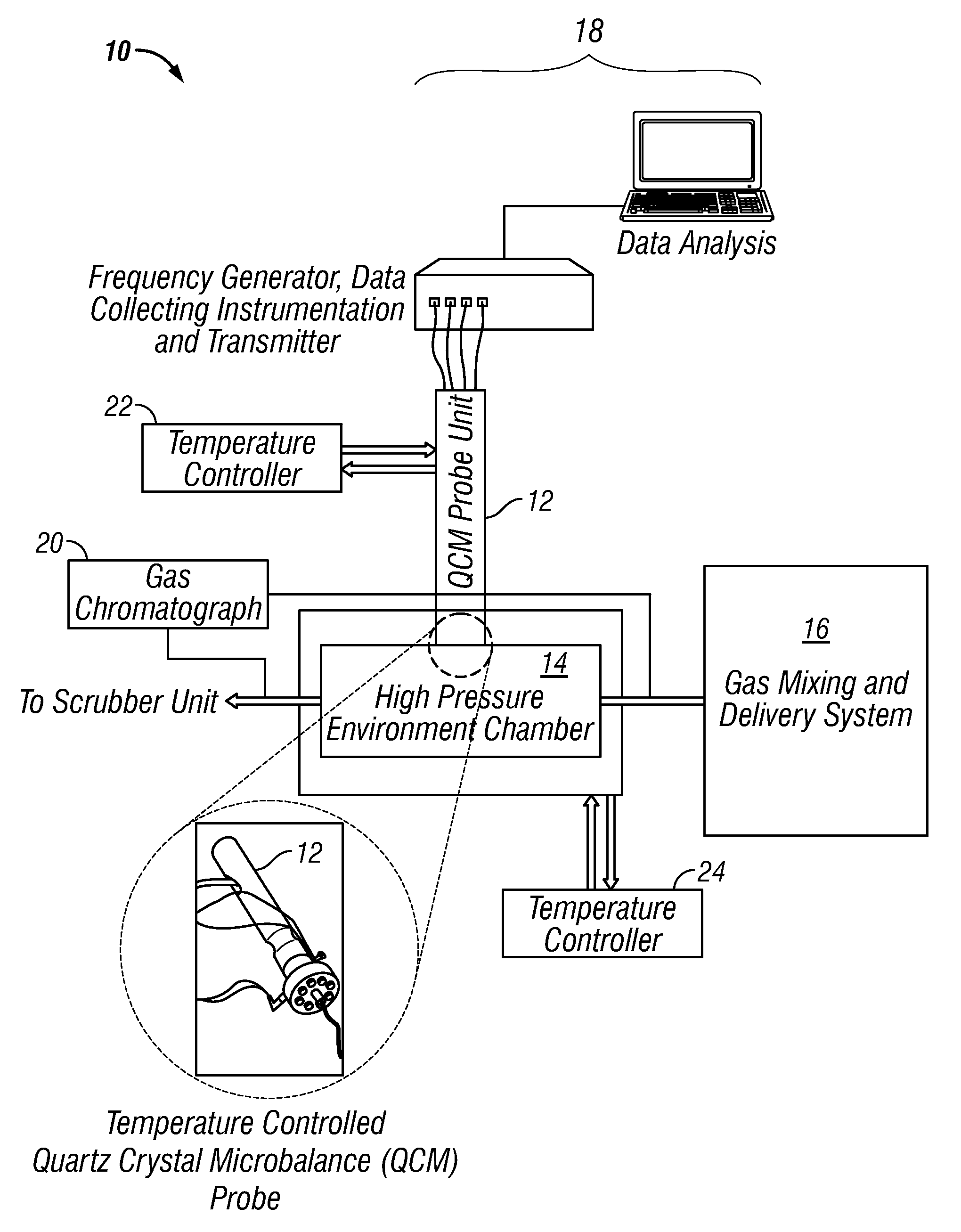
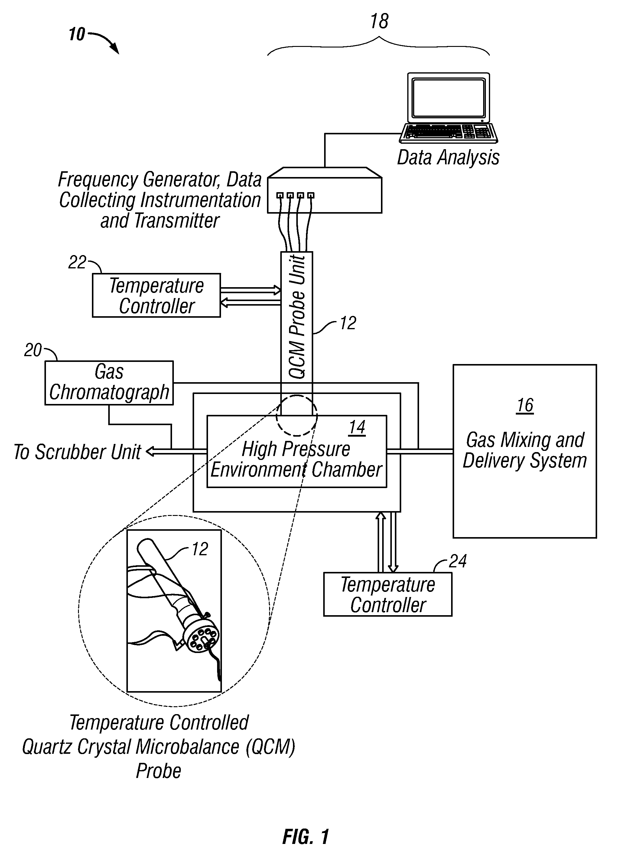
[0043]A QCM probe coated with thin film of iron would be placed in a temperature-controlled high pressure gas chamber and maintained at a constant temperature (which would be lower than temperature of the gas chamber) for induced water condensation (condensation cycle). The condensed water would result in an increase in weight of the QCM probe. The condensed water on the iron-coated QCM probe with absorbed gases (CO2, H2S, O2) would cause the iron to corrode leading to further weight gain of the QCM. After subsequent increase in temperature of the QCM probe the water layer would evaporate (evaporation cycle) resulting in a net weight gain due to black powder formed during the condensation cycle. In these experiments, the temperature of the gas chamber would be varied between 5 and 50° C. while pressure would be maintained between 15 and 1000 psi (0.1 to 6.9 MPa). The temperature differential between the QCM and the gas chamber would be in the range from 0 to 50° C.

[0044]Many modific...


PUM


Abstract

Solids deposition in a gas environment, such as a gas transmission line or pipeline are measured using metal-coated quartz crystal microbalance (QCM) in a QCM probe within a high pressure gas chamber in the gas environment. The metal coated on the QCM may be iron, iron alloys and/or iron oxide. The weight measurements are conducted at a constant (ΔT) or controlled (T=f(t)) temperature between the high pressure gas chamber and the QCM probe. The weight gain during a CE cycle is associated with the solids formation rate.

Description

CROSS-REFERENCE TO RELATED APPLICATION[0001]This application claims the benefit of U.S. Provisional Patent Application 61 / 031,740 filed Feb. 27, 2008.TECHNICAL FIELD[0002]The invention relates to methods and apparatus for measuring solids deposits in a gas environment, and most particularly relates, in one non-limiting embodiment, to methods and apparatus for measuring the formation of “black powder” in gas transmission lines.TECHNICAL BACKGROUND[0003]“Black powder” formation in gas transmission lines, such as sales gas lines, is a problem that has had a serious impact on pipeline operations including, but not necessarily limited to, erosion failures of valves, lower efficiency of compressors, clogging of instrumentation and valves, and problems with Health, Safety & Environment (HS&E) compliance. Despite the fact that this has been a persistent problem in the industry, there has been little work towards ascertaining the composition, sources and formation mechanism of black powder i...

Claims


Application Information

Patent Timeline
IPC IPC(8): G01N30/02G01N37/00
CPCG01G3/16G01N17/008G01N2030/025G01N2291/0256G01N29/022G01N5/04G01N2291/02408G01N25/68
Inventor JOVANCICEVIC, VLADIMIRRAMACHANDRAN, SUNDERHAMMONDS, PAUL
Owner BAKER HUGHES INC
Why Eureka
Try Eureka