Heat sink structure

a technology of heat sink and heat sink body, which is applied in the direction of lighting and heating apparatus, semiconductor devices, and semiconductor/solid-state device details. it can solve the problems of reducing the service life of computer devices, reducing the stability and efficiency of electronic components, and increasing the amount of thermal energy generated by small volume of electronic components. it achieves poor thermal dissipation performance and improves thermal cycling performan

Inactive Publication Date: 2009-08-27
INVENTEC CORP
View PDF5 Cites 12 Cited by
  • Summary
  • Abstract
  • Description
  • Claims
  • Application Information

AI Technical Summary

Benefits of technology

[0012]The heat sink of the present invention utilizes the displacement such as inclination or swing generated when the electronic device is operated to make the fin base with its center of gravity deviating from the rotation axis to rotate, thereby disturbing the air inside the electronic device and improving the thermal cycling performance, such that the thermal energy generated by the electronic component can be dissipated quickly. The present invention solves the problem of the conventional heat sink applied to the portable electronic device that the overall thermal dissipation performance is poor since a forced airflow cannot be generated for exchanging thermal.

Problems solved by technology

However, the rapid operation speed of the electronic components inside the computer device, and the small volume of the electronic components incur a higher thermal energy generation amount per units.
If the generated thermal energy cannot be dissipated in time, the over-high temperature will seriously influence the stability and efficiency of the electronic components in operation, and even reduce the service life of the computer device or cause damage to the computer device.
Therefore, it is difficult to install an additional heat sink fan in the portable computer device with limited free space.
Consequently, the portable computer device without the design of fan cannot utilize the forced convection of air, and relies only on the natural convection and thermal radiation between the heat sink and the air to dissipate thermal energy, and thus the thermal dissipation effect is unsatisfactory, and cannot meet the thermal dissipation requirements of the portable electronic apparatus with high operation speed.
Although the thermal energy generated by the portable computer device in operation may be reduced by lowering the operating frequency of the electronic components, the overall performance of the computer device is influenced, which does not meet the demands of the consumers for high operating performance of the electronic products.
Also, the thermal dissipation of the electronic device relying only on the natural convection and thermal radiation is insufficient.
The increased thermal dissipation surface area for dissipating thermal energy leads to the increase of the overall volume of the computer device, such that the portable computer device cannot be miniaturized, which is against the current trend of light, thin, short, and small electronic products in the market.

Method used


Image

  • Heat sink structure
  • Heat sink structure
  • Heat sink structure

Examples


Embodiment Construction

[0023]The heat sink provided by the present invention is used to dissipate the thermal energy generated by the electronic device which likes an UMPC, a personal computer, a notebook computer, a PDA, but not limit to the above-mentioned portable electronic devices. In the following detailed description of the present invention, UMPC is taken as a preferred embodiment of the present invention, and the accompanying drawings are used to provide reference and illustration, and not intended to limit the present invention.

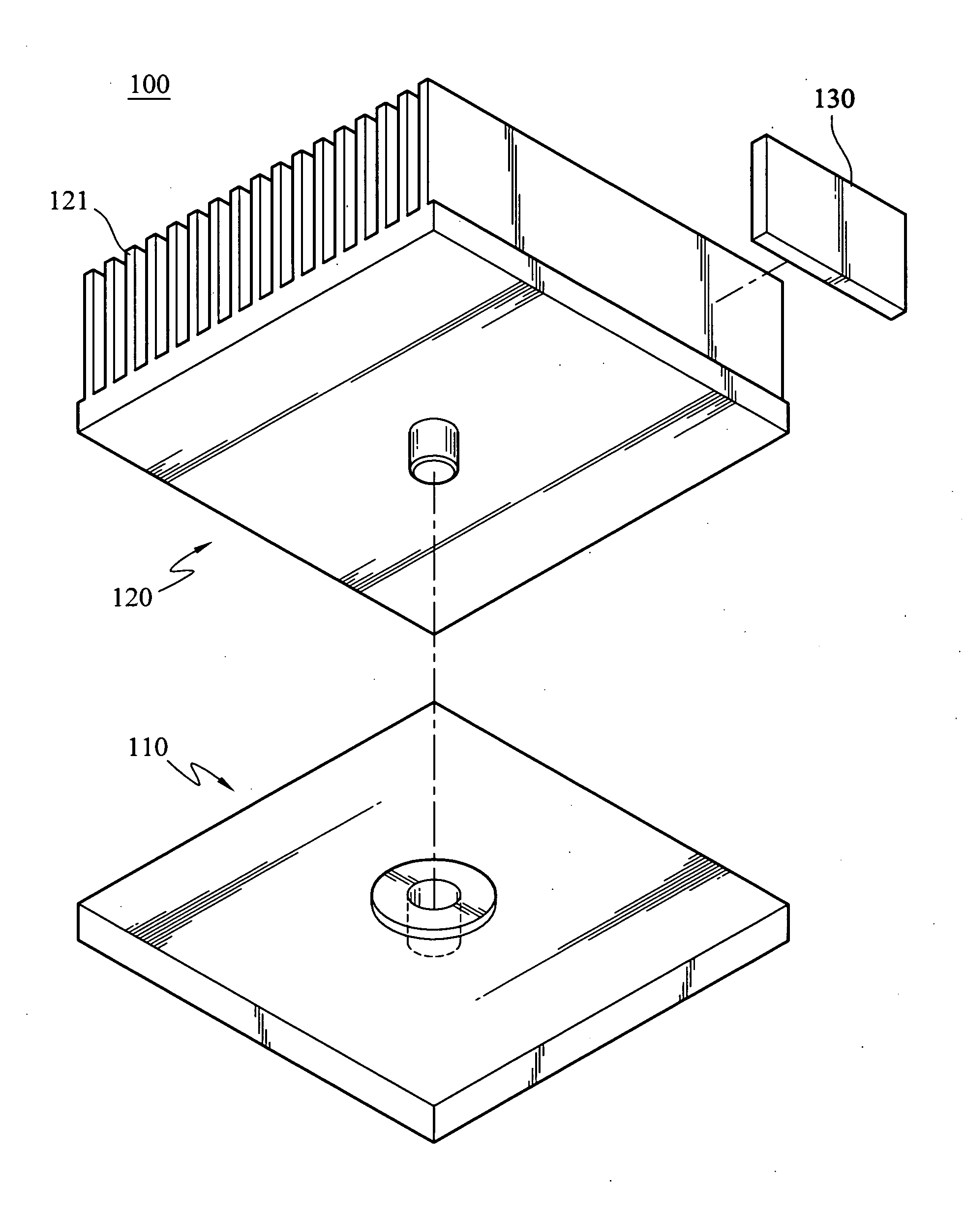
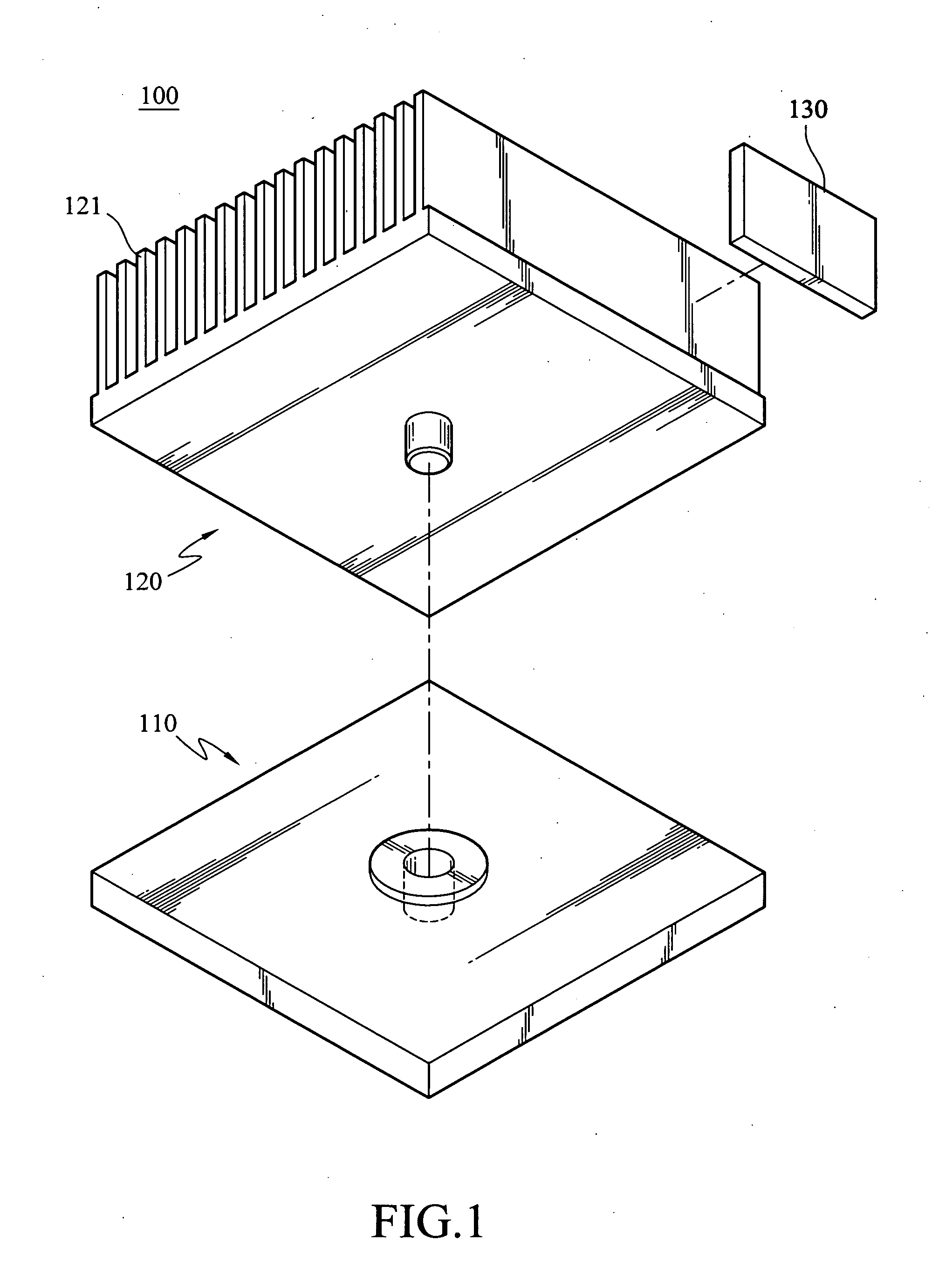
[0024]FIG. 1 is an exploded view of a heat sink of the present invention. A heat sink 100 of the present invention includes a contact base 110, a fin base 120, and a balance weight 130. The shape of the heat sink 100 provided by the present invention is rectangular, similar to that of the conventional heat sink. The contact base 110 is attached on an electronic component (not shown), and the fin base 120 is pivotally connected to the contact base 110, so as to transfer th...


PUM


Abstract

A heat sink is used for dissipating thermal energy generated by an electronic component of an electronic device. The heat sink includes a contact base and a fin base. The contact base is attached on the electronic component to transfer thermal energy, and the fin base is pivotally connected to the contact base to transfer thermal energy with the contact base. The fin base has a plurality of fins, and rotates relative to the contact base. A center of gravity of the fin base deviates from a rotation axis. When the electronic device is moved, due to the deviated center of gravity, the fin base rotates to make the fins disturb the air inside the electronic device.

Description

BACKGROUND OF THE INVENTION[0001]1. Field of Invention[0002]The present invention relates to a heat sink. More particularly, the present invention relates to a heat sink applied to a portable electronic device.[0003]2. Related Art[0004]Currently, with the rapid development of electronic science and technology, and the increasing attention that consumers pay to light, thin, and portable characteristics of consumable electronic products, electronic products, e.g. notebook computers, ultra mobile personal computers (UMPC), PDAs, and other portable electronic devices, are gradually developed toward miniaturization. For users who often travel outside, the portable electronic products are more convenient to carry, thus greatly improving the convenience in use.[0005]However, the rapid operation speed of the electronic components inside the computer device, and the small volume of the electronic components incur a higher thermal energy generation amount per units. If the generated thermal e...

Claims


Application Information

Patent Timeline
Patent Type & Authority Applications(United States)
IPC IPC(8): F28F7/00
CPCH01L23/367H01L23/467H01L2924/0002H01L2924/00
Inventor WANG, FENG-KUWANG, SHAW-FUUHUANG, TING-CHIANGSYU, SHENG-JIE
Owner INVENTEC CORP
Why Eureka
Try Eureka