
Receiver for amplitude-modulated signals

a technology of amplitude modulation and receiver, applied in the direction of modulation transference, transmission, electric devices, etc., can solve the problems of phase control error and adversely affect the reception quality, and achieve the effect of less interference risk, cost saving and improved reception quality

Active Publication Date: 2009-08-27
III HLDG 6
View PDF10 Cites 4 Cited by
  • Summary
  • Abstract
  • Description
  • Claims
  • Application Information

AI Technical Summary

Benefits of technology

[0010]Another advantage of the invention relates to the following aspects. As explained hereinbefore, a phase detection in accordance with the invention is relatively insensitive to parasitic direct current signals. This makes the invention particularly suitable for use in direct conversion receivers, which generally suffer from parasitic direct current signals. Direct conversion receivers have various advantages. In a direct conversion receiver, a single oscillator can carry out a frequency conversion as well as a demodulation. In general, each oscillator in a receiver may produce parasitic signals, which may interfere with a desired signal. Since a direct conversion receiver requires relatively few oscillators, there is less risk of interference, which allows a better reception quality. Another advantage is that direct conversion receivers can generally be implemented as an integrated circuit with relatively few external components, which is cost efficient. Since the invention allows direct conversion receivers that are less sensitive to parasitic direct current signals, the invention allows low-cost receiver implementations that provide satisfactory reception quality.
[0011]These and other aspects of the invention will be described in greater detail hereinafter with reference to drawings.

Problems solved by technology

The parasitic direct current signal will introduce a phase control error in the sense that the static phase difference may be set to a value that is relatively far from a desired value for which reception quality is optimal.
Consequently, the parasitic direct current signal, which the mixer circuit provides, adversely affects reception quality unless special measures are taken.

Method used


Image

  • Receiver for amplitude-modulated signals
  • Receiver for amplitude-modulated signals
  • Receiver for amplitude-modulated signals

Examples


Embodiment Construction

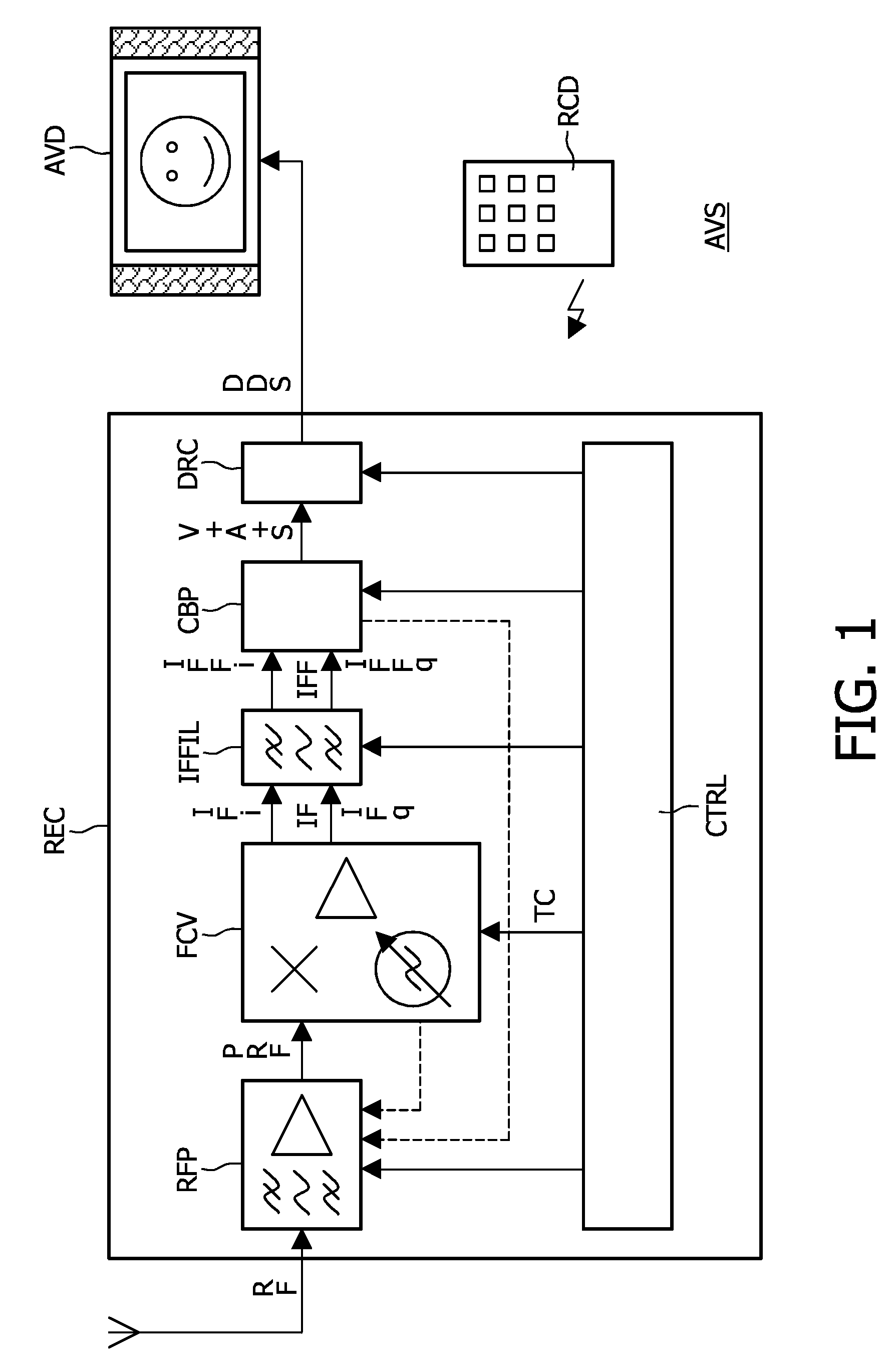
[0015]FIG. 1 illustrates an audiovisual system AVS. The audiovisual system AVS comprises a receiver REC, an audiovisual rendering device AVD, and a remote control device RCD. The audiovisual rendering device AVD may be, for example, a flat panel display with stereo loudspeakers. The receiver REC causes the audiovisual rendering device AVD to render an audiovisual signal from a television (TV) station that a user has selected.

[0016]The receiver REC comprises a radiofrequency processor RFP, a frequency converter FCV, an intermediate frequency filter IFFIL, a composite baseband processor CBP, a driver circuit DRC, and a controller CTRL. The intermediate frequency filter IFFIL may be a so-called polyphase filter, which allows a frequency response that is asymmetrical with respect to zero (0) frequency. The controller CTRL may be in the form of a suitably programmed microcontroller. The radiofrequency processor RFP and the frequency converter FCV may form part of a single integrated circ...


PUM


Abstract

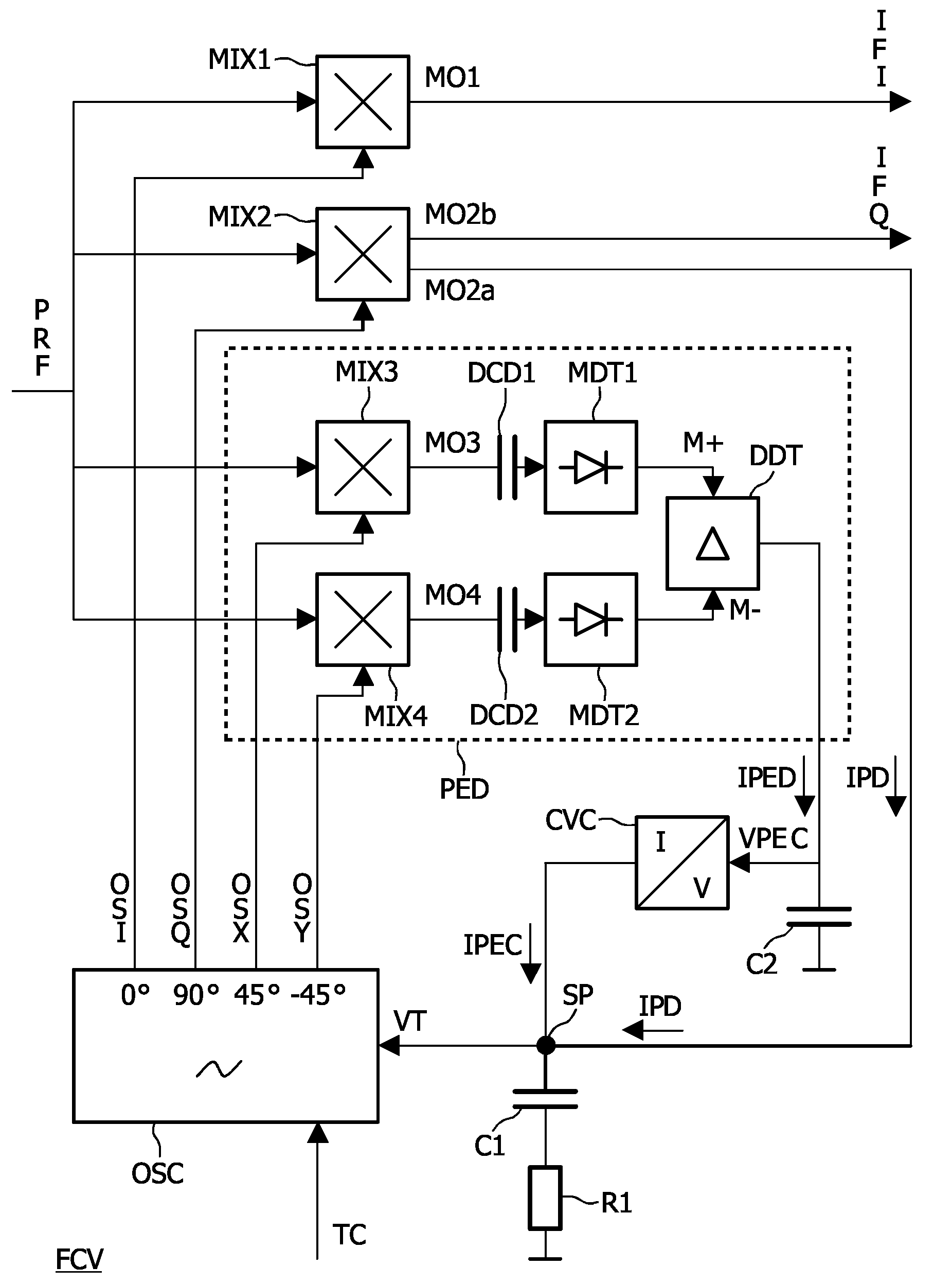
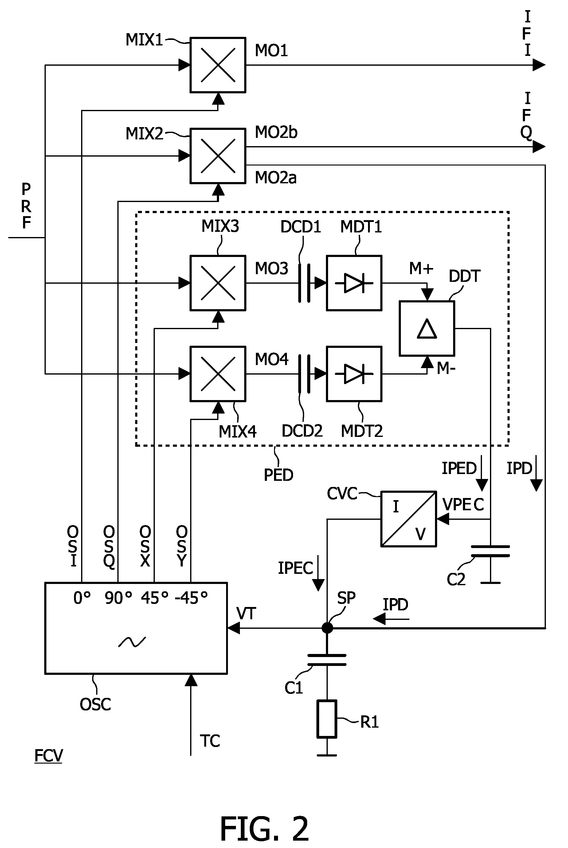
In a receiver, a synchronization circuit (MIX2, C1, R1, VCO) provides a set of oscillator signals (OSI, OSQ, OSX, OSY) that are synchronized with a carrier of an amplitude-modulated signal. The set of oscillator signals (OSI, OSQ, OSX, OSY) comprises a first amplitude-demodulation oscillator signal (OSX) and a second amplitude-demodulation oscillator signal (OSY) that differ in phase. A first amplitude-demodulation mixer (MIX3) mixes the first amplitude-demodulation oscillator signal (OSX) with the amplitude-modulated signal so as to obtain a first amplitude-demodulated signal (MO3). A second amplitude-demodulation mixer (MIX4) mixes the second amplitude-demodulation oscillator signal (OSY) with the amplitude-modulated signal so as to obtain a second amplitude-demodulated signal (MO4). A magnitude comparator (MDT1, MDT2, DDT) compares respective magnitudes (M+, M−) of the first amplitude-demodulated signal (MO3) and the second amplitude-demodulated signal. Accordingly, a phase-error detection signal (IPED) is obtained that varies as a function of a difference between the respective magnitudes (M+, M−) of the first amplitude-demodulated signal (MO3) and the second amplitude-demodulated signal (MO4).

Description

FIELD OF THE INVENTION[0001]An aspect of the invention relates to a receiver for amplitude-modulated signals, such as, for example, television signals. The receiver may be, for example, a conventional television set, a settop box, a digital video recorder, a personal computer or any other multimedia apparatus. Other aspects of the invention relate to a method of controlling a receiver, a computer program product for a receiver, and an audiovisual system.DESCRIPTION OF PRIOR ART[0002]U.S. Pat. No. 4,631,499 describes a phaselock loop that can be used to generate a synchronous RF carrier in a directly mixing AM receiver. The phaselock loop comprises a phase detection arrangement that reduces an unwanted DC offset generated during phase detection. The phase detection arrangement comprises three cascade-coupled mixer stages. Two of these mixer stages receive an auxiliary mixing signal that has a relatively low frequency.SUMMARY OF THE INVENTION[0003]According to an aspect of the inventi...

Claims


Application Information

Patent Timeline
IPC IPC(8): H04B1/16
CPCH03D3/241H04B1/30H03D7/165
Inventor FORTUIN, ROB
Owner III HLDG 6
Learn More