DC converter which has switching control unit to select PWM signal or PFM signal

a technology of dc converter and switching control unit, which is applied in the direction of dc-dc conversion, power conversion system, instruments, etc., can solve the problems of inability to accommodate a wide range of changes, increase in power consumption due to load rl,

Inactive Publication Date: 2009-09-03
RENESAS ELECTRONICS CORP
View PDF6 Cites 53 Cited by
  • Summary
  • Abstract
  • Description
  • Claims
  • Application Information

AI Technical Summary

Benefits of technology

[0016]According to another exemplary aspect of the DC converter of the present invention, the DC converter can detect an increasing tendency of power consumption at a load in accordance with a fact that power consumption at a load has increased and a pulse output interval of a PFM pulse signal has shortened, and can switch from pulses driving a drive circuit to a PWM pulse signal.

Problems solved by technology

Therefore, there is a problem that an increase in power consumption due to a load RL cannot be accommodated.
In other words, there is a problem that the switching regulator 100 described in Patent Document 1 cannot accommodate a wide range of changes in power consumption due to the load RL.

Method used


Image

  • DC converter which has switching control unit to select PWM signal or PFM signal
  • DC converter which has switching control unit to select PWM signal or PFM signal
  • DC converter which has switching control unit to select PWM signal or PFM signal

Examples


exemplary embodiment 1

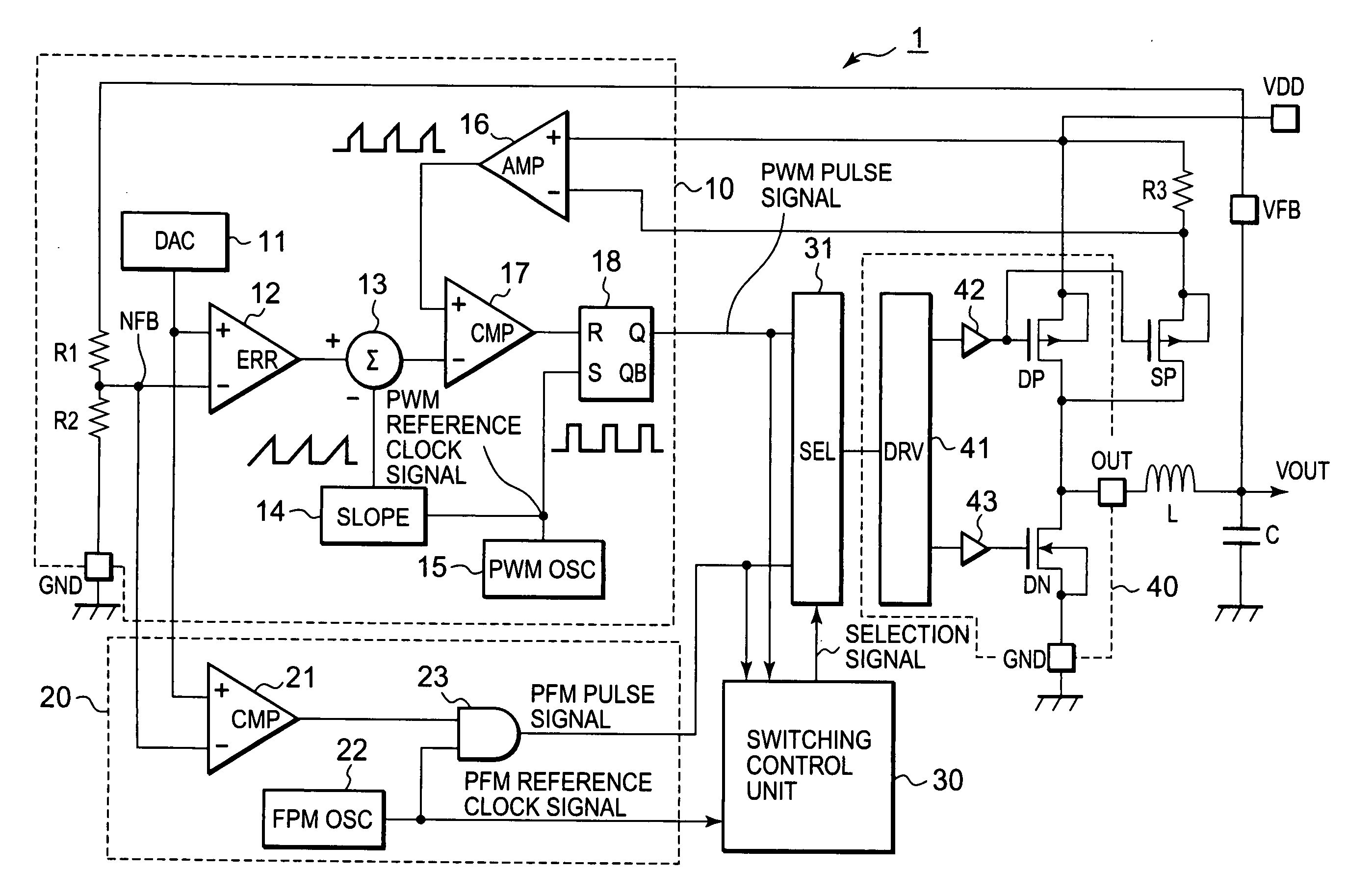
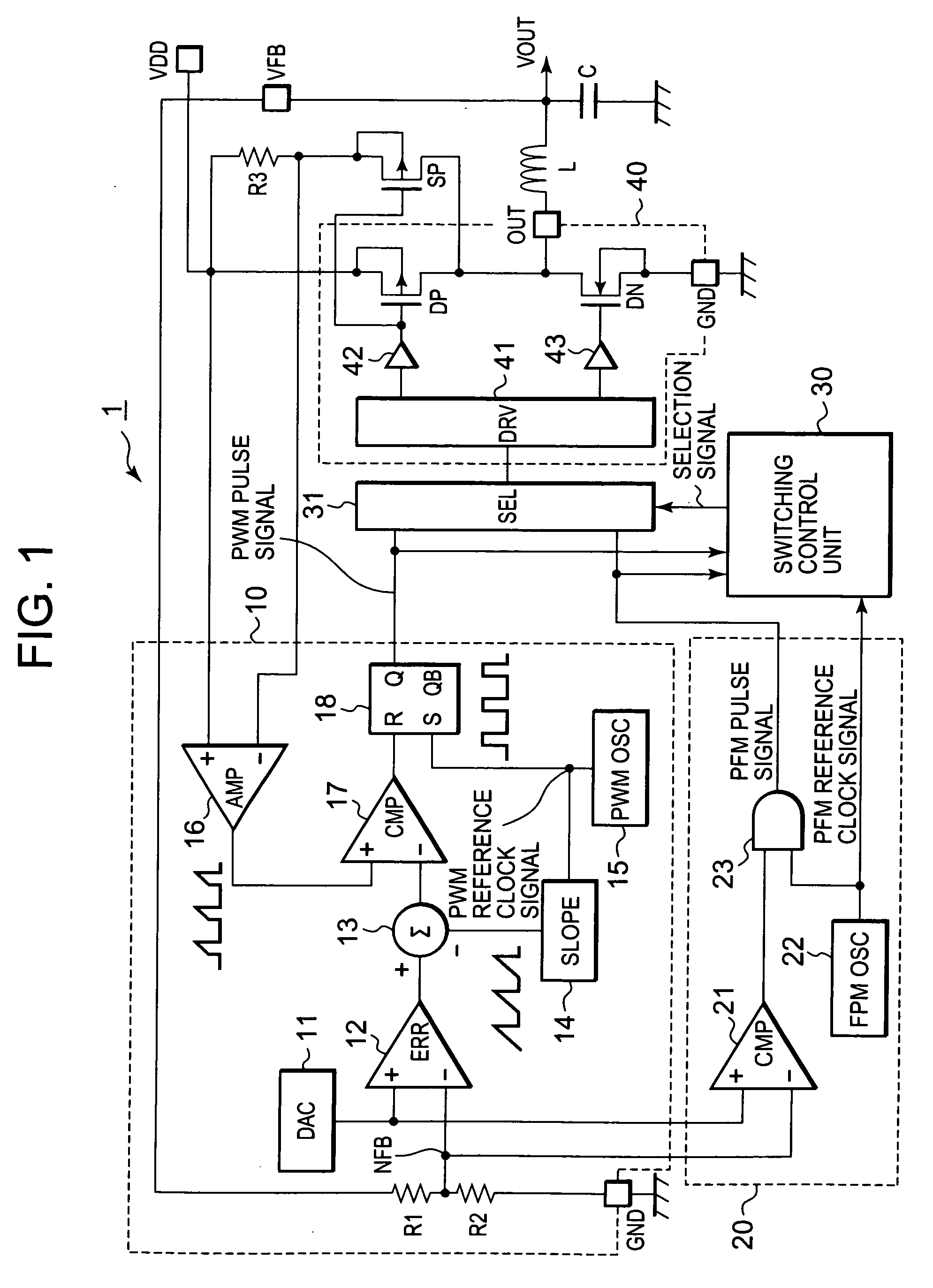
[0027]FIG. 1 shows a block diagram of a DC converter 1 according to the exemplary embodiment. As shown in FIG. 1, the DC converter 1 includes a PWM pulse generation unit 10, a PFM pulse generation unit 20, a switching control unit 30, a selection circuit 31, a drive circuit unit 40, a sense transistor SP, and a resistor R3. Furthermore, the DC converter 1 includes a power terminal VDD, a feedback terminal VFB, an output terminal OUT, and a ground terminal GND. An output voltage VOUT is generated by charging a capacitor C via an inductor L connected to the output terminal OUT.

[0028]The PWM pulse generation unit 10 outputs a PWM pulse signal whose duty ratio is controlled in accordance with the output voltage VOUT. The PWM pulse generation unit 10 includes resistors R1 and R2, a DAC (Digital Analog Converter) 11, an error amplifier 12, a subtracter 13, a sawtooth wave generation unit 14, a PWM reference clock generation unit 15, an amplifier 16, a comparator 17, and a set / reset latch ...

exemplary embodiment 2

[0065]FIG. 5 shows a block diagram of a DC converter 2 according to a second exemplary embodiment. As shown in FIG. 5, the DC converter 2 includes a switching control unit 30a whose configuration is different from that of the switching control unit 30 of the DC converter 1 according to the first exemplary embodiment. A PWM reference clock signal is added as an input signal to the switching control unit 30a. FIG. 6 shows a block diagram of the switching control unit 30a.

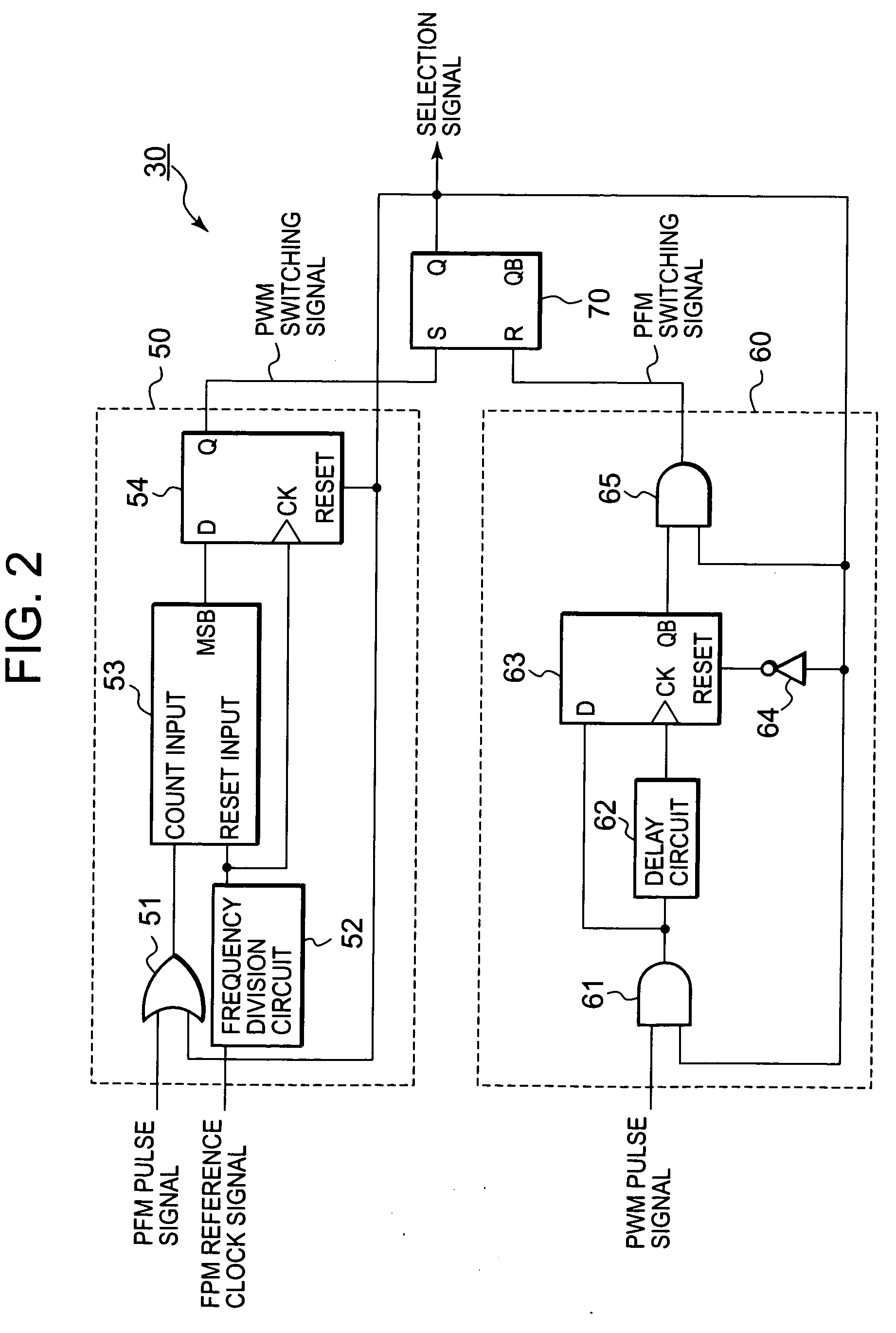
[0066]As shown in FIG. 6, the switching control unit 30a includes a pulse number detection unit 50 and a state maintaining circuit 70, which have the same configurations as those of the switching control unit 30 in the first exemplary embodiment, and a duty detection unit 80, which has a different configuration from that of the duty detection unit 60 of the switching control unit 30.

[0067]The duty detection unit 80 essentially operates in the same manner as the duty detection unit 60, but signal used for the detectio...


PUM


Abstract

A DC (direct current) converter includes a PWM (pulse width modulation) pulse generation unit outputting a PWM pulse signal whose duty ratio is controlled in accordance with an output voltage, a PFM (pulse frequency modulation) pulse generation unit outputting a PFM pulse signal whose pulse output interval is controlled in accordance with an output voltage, a selection circuit selecting and outputting any one of the PWM pulse signal and the PFM pulse signal in response to a selection signal, a drive circuit unit driving a load and generating an output voltage on the basis of a signal outputted from the selection circuit, and a switching control unit outputting the selection signal. When the selection signal is in a second state, the switching control unit detects a fact that the number of pulses of the PFM pulse signal in a measurement period increases to or above a set value of the maximum number of pulses, and switches the selection signal to a first state.

Description

BACKGROUND OF THE INVENTION[0001]1. Field of the Invention[0002]A DC converter according to the present invention particularly relates to a DC converter which supports a first drive method using a PWM (Pulse Width Modulation) pulse signal and a second drive method using a PFM (Pulse Frequency Modulation) pulse signal.[0003]2. Description of Related Art[0004]In recent years, a DC converter has often been used as a power control circuit in an electronic circuit. A DC converter is a voltage converter which is supplied with a DC voltage as an input voltage and then outputs an output voltage having a different voltage value. As an example of a DC converter, there is a switching regulator generating an output voltage by driving an output transistor on the basis of a pulse signal. Switching regulators are widely used due to the high efficiency of power conversion.[0005]An example of the switching regulator is disclosed in Patent Document 1. FIG. 8 shows a block diagram of a switching regul...

Claims


Application Information

Patent Timeline
Patent Type & Authority Applications(United States)
IPC IPC(8): G05F1/00
CPCH02M3/156
Inventor KIKUCHI, HIDEHIRO
Owner RENESAS ELECTRONICS CORP
Why Eureka
Try Eureka