Wing and blade structure using pultruded composites

a composite material and composite material technology, applied in the field of composite materials, can solve the problems of large performance gap, high bending stress of aircraft wing and blade structures, and low compression strength of carbon composite materials, so as to achieve high stress, increase compressive strength, and increase compressive strength

Active Publication Date: 2009-09-03
KAREM ABE
View PDF9 Cites 62 Cited by
  • Summary
  • Abstract
  • Description
  • Claims
  • Application Information

AI Technical Summary

Benefits of technology

[0012]Especially preferred embodiments include aircraft structural components such as wings, wing spars, wing skins, fuselage skins, rotor blades, propellers, and propeller blades. These components are often highly stressed structures and can benefit from increased compressive strength.
[0013]Preferred laminates can be constructed to have at least 6, 10, 30, 50, or 100 layers of material, and can have a maximum thickness of at least 0.15, 0.25, 0.5, 1.0, or 5.0 inches. It is contemplated that one layer in a preferred laminate could have fibers predominantly aligned in one direction, while another layer could have fibers predominantly aligned in another direction. This heterogeneous fiber layout allows for tailoring of the strength of a composite structure. In some embodiments, such as angled or kinked joints, layers in a laminate might have long axes in different directions, at least 100, 300, 600, 900, or 1200 apart.
[0014]Viewed from another aspect, the present inventive subject matter can provide for increased compressive strength in a composite laminate by including a layer with pultruded fibers which vary in thickness by at least 10%, 30%, or 60% along its length, and tapering the thickness of the composite laminate by at least 40%, 60%, or 80% from a maximum thickness. In more preferred embodiments, additional layers with pultruded fibers or other pultruded material could be included in the laminate. In especially preferred embodiments, the fibers are graphite fibers, and the composite layers have a thickness of 10 / 1000, 15 / 1000, 20 / 1000, or 25 / 1000 inch.
[0015]It is contemplated that laminates can have one or more layers which advantageously taper at a 10:1, 20:1, 40:1, or shallower slope. Further, preferred laminates can comprise additional layers of biased pre-preg tape to provide shear strength and shear stiffness.

Problems solved by technology

Although carbon composite materials do provide weight savings over traditional aluminum structures, carbon composite materials still suffer from a comparatively low compression strength.
Aircraft wing and blade structures in particular see high bending stresses due to the cantilevered configuration of their structure, and the thin sections required for aerodynamic performance.
Thus, although composite materials do increase the structural efficiency (ratios of strength to weight or stiffness to weight) of aircraft structures over a typical aluminum structure, there is still a large performance gap that can be bridged by increasing the compression strength of the composite laminate.
Typical distributed loads on a cantilevered structure such as a wing result in a moment that drops off rapidly from the root to the tip of the structure.
The resulting stress riser fails the nearby supporting matrix material and ultimately cause a failure of the laminate.

Method used


Image

  • Wing and blade structure using pultruded composites
  • Wing and blade structure using pultruded composites
  • Wing and blade structure using pultruded composites

Examples


Embodiment Construction

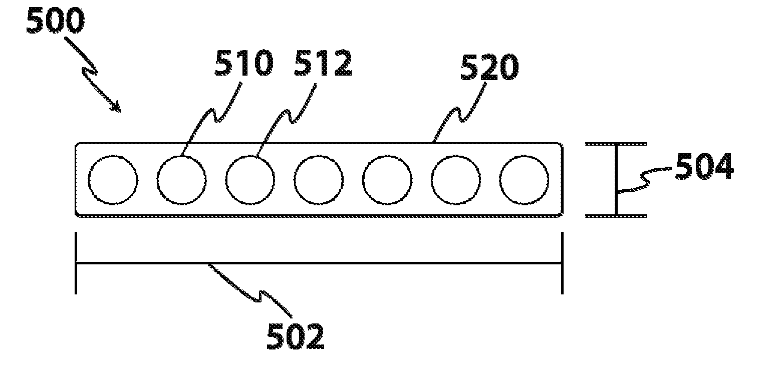
[0025]As shown in the drawing figures discussed below, pultruded fibers can be integrated into a highly-stressed tapered beam structure such as a structurally efficient aircraft wing, rotor blade, or propeller. Pre-cured pultruded material is advantageously laminated into a composite aircraft spar structure adding high compressive strength material to areas where it is most effective, thereby reducing aircraft weight and increasing structural capacity.

[0026]As used herein, “composite” means engineered materials comprising two or more constituent materials. Of special relevance is carbon composites, in which carbon fiber is embedded in a matrix or resin. Alternate composites are also contemplated, including those containing fiberglass, ceramics, and other elements. A layer of composite material could include a plurality of fibers positioned at an orientation with respect to the long axis of an object. A layer of composite material could also advantageously include pultruded fibers in...


PUM

PropertyMeasurementUnit
thicknessaaaaaaaaaa
anglesaaaaaaaaaa
anglesaaaaaaaaaa

Abstract

Tapered layers of pre-cured composite material are integrated into a tapered, highly stressed laminate structure in order to provide improved compressive strength. The pre-cured composite material can advantageously be cured under tension as pultruded material, to further augment compressive strength. The thickness of composite layers can be tapered on their termination edges by mechanically abrading, chemical abrading, or other methods. Especially preferred embodiments include aircraft structural components such as wings, wing spars, wing skins, fuselage skins, rotor blades, propellers, and propeller blades. Preferred laminates can be constructed to have at least 6, 10, 30, 50, or 100 layers of material, and can have a maximum thickness of at least 0.15, 0.25, 0.5, 1.0, or 5.0 inches.

Description

[0001]This application claims priority to U.S. provisional application Ser. No. 61 / 033,337, filed Mar. 3, 2008, the disclosure of which is incorporated herein in its entirety.FIELD OF THE INVENTION[0002]The field of the invention is composite structures.BACKGROUND[0003]Due to the nature of flight, desirable aircraft structures have traditionally had high strength-to-weight ratios (strength efficiency) and stiffness-to-weight ratios (stiffness efficiency). In the last several decades, carbon composite materials were often used in aircraft structures to improve strength and stiffness efficiency in the airframe. Although carbon composite materials do provide weight savings over traditional aluminum structures, carbon composite materials still suffer from a comparatively low compression strength. In a typical unidirectional carbon composite laminate the compression strength is approximately 50% of the tension strength of the material. This is caused by small amplitude waviness in the un...

Claims


Application Information

Patent Timeline
Patent Type & Authority Applications(United States)
IPC IPC(8): B32B3/00B29C47/00
CPCB29C70/52B29C70/545B29C70/683B29C70/865Y10T428/24124B32B5/28B64C3/185Y02T50/433Y10T428/24612B29L2031/3076B32B3/263B32B5/022B32B5/024B32B5/12B32B5/26B32B2250/44B32B2260/021B32B2260/046B32B2262/0269B32B2262/10B32B2262/101B32B2262/105B32B2262/106B32B2307/50B32B2307/54B32B2307/546B32B2307/718B32B2603/00B32B2605/18Y02T50/40
Inventor KAREM, ABE
Owner KAREM ABE
Why Eureka
Try Eureka