Eureka AIR delivers breakthrough ideas for toughest innovation challenges, trusted by R&D personnel around the world.

Unglazed photovoltaic and thermal apparatus and method

a photovoltaic and thermal apparatus technology, applied in the field of solar energy panels, can solve the problems of insulating glazing, gap left between the pv array and the transparent sheet, and the performance of pv and thermal collectors separately optimized for their applications, so as to achieve the effect of reducing the insulating glazing, reducing the temperature, and improving the efficiency

Inactive Publication Date: 2009-09-10
COX EDWIN B
View PDF45 Cites 40 Cited by
  • Summary
  • Abstract
  • Description
  • Claims
  • Application Information

AI Technical Summary

Benefits of technology

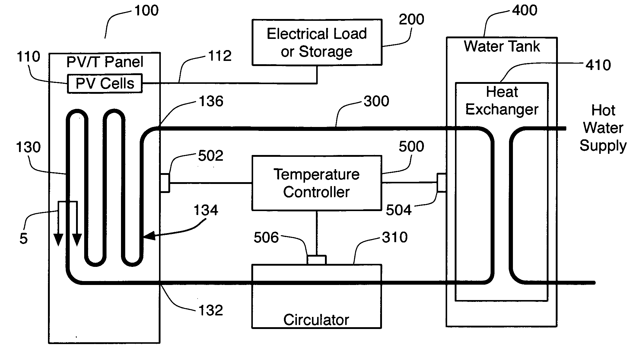
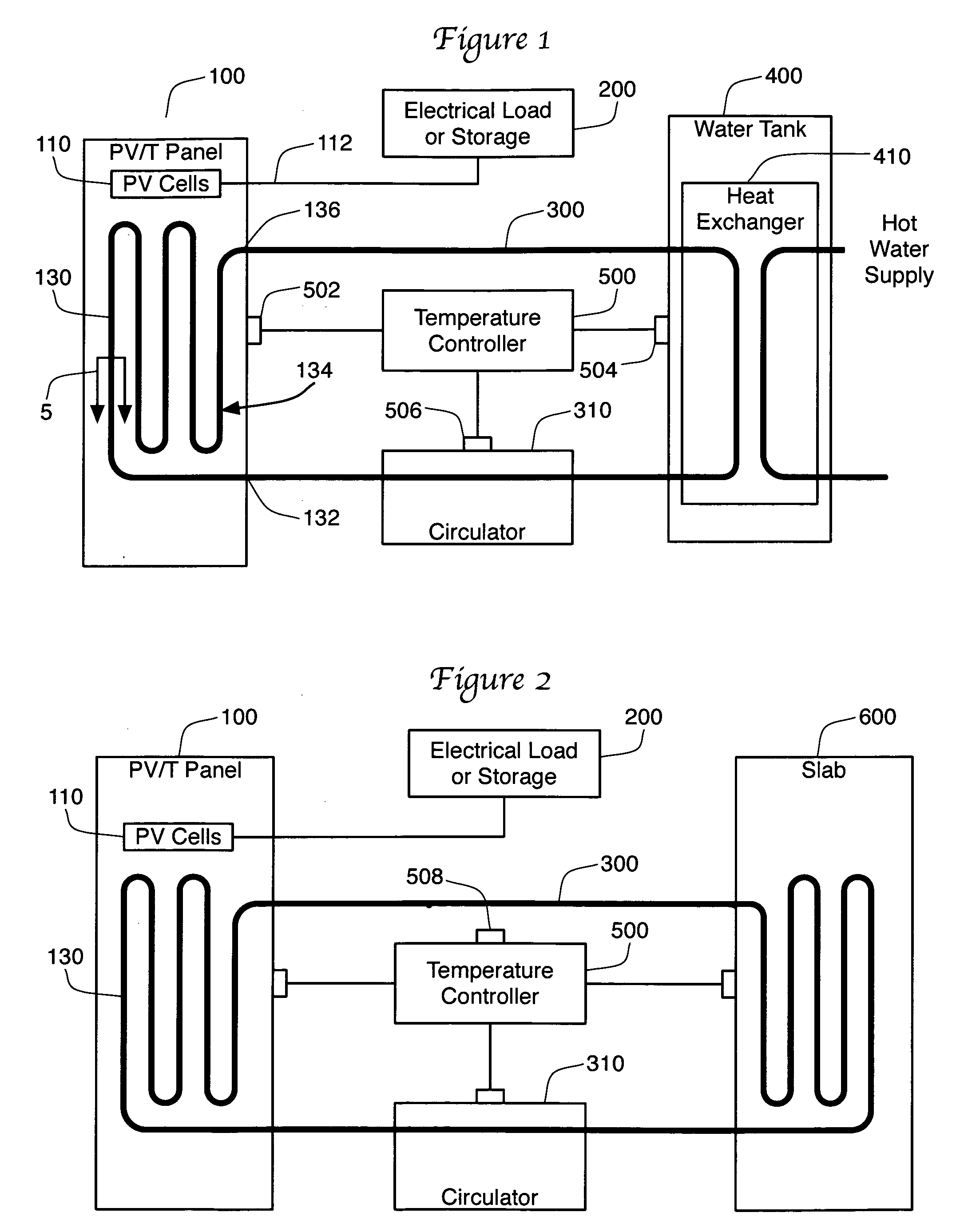
[0008]The present invention discloses a combination photovoltaic and thermal solar energy panel. This PV / T panel improves upon the prior art by recognizing the need to eliminate insulative glazing from the panel. The absence of insulative glazing allows the photovoltaic cells to operate at a lower temperature and therefore at a higher efficiency. In addition, the absence of insulative glazing or any other transparent layer that is not in thermal contact with the PV array allows the present invention PV / T panel to be used to provide nighttime cooling for a building.

Problems solved by technology

The majority of the solar energy incident upon a PV array goes to waste in the form of heat.
These types of collectors are well known in the art but have heretofore not been able to match the performance of PV and thermal collectors separately optimized for their applications.
However, where there is an insulative glazing, a gap is left between the PV array and the transparent sheet.
The specified use of copper exacts a substantial cost in price of the material, weight added to the system and complexity of fabrication (soldering, brazing, etc).
Since this gap is not part of a sealed system, the lens is not technically an insulative glazing as outside air is allowed to flow between the lens and the PV array.
Nonetheless, this transparent layer is not in thermal contact with the PV array, and therefore this layer substantially hinders the outward flow of long-wave infrared radiation from the PV array.
The fluid partitions make this type of array difficult to construct and maintain when compared to a tubing system.

Method used


Image

  • Unglazed photovoltaic and thermal apparatus and method
  • Unglazed photovoltaic and thermal apparatus and method
  • Unglazed photovoltaic and thermal apparatus and method

Examples


Embodiment Construction

Recognition of the Problem

[0016]Prior art PV / T systems work by using an insulative glazing to retain heat within the panel. This heat retention allows the heat transfer fluid that removes heat from the panel to reach a higher temperature. This in turn extends the range of potential applications and allows heat to be carried away from the panel at lower fluid flow rates. However, as recognized by the applicant, the use of higher working temperatures in the PV / T panel comes at a significant cost. The differential coefficients of thermal expansion of insulative glazing and frame require intricate provisions to maintain sealing integrity under the wide temperature variations encountered. Evacuation of gas from the enclosure or instillation of an inert gas is also usually required to prevent PV deterioration. These measures add to the weight, complexity, cost and maintenance requirements of glazed PV / T systems, thus decreasing their practical application while also compromising the elect...


PUM


Abstract

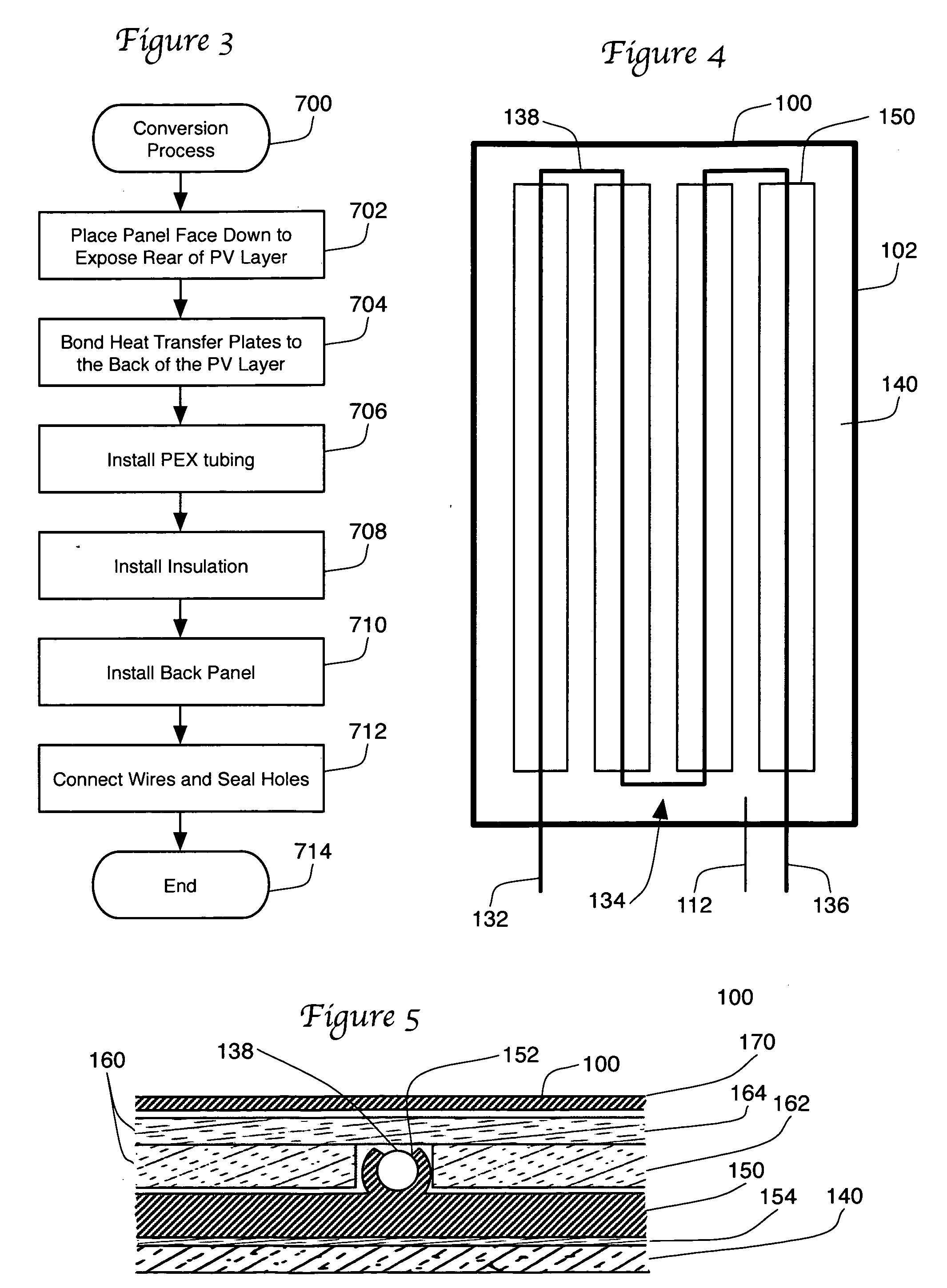
A photovoltaic / thermal solar panel is presented which contains no glazing above the photovoltaic array. The absence of glazing allows the photovoltaic cells to operate at a lower temperature and therefore at a higher efficiency. In addition, the absence of glazing allows the present invention PV / T panel to be used to provide nighttime cooling for a building. The panel is constructed by adhering an aluminum heat transfer plate to the rear of the PV array in the panel using a silicone adhesive. PEX tubing is inserted into channels integrally formed into the back of the heat transfer plate again using silicone or other heat-conductive compound.

Description

FIELD OF THE INVENTION[0001]The present invention relates to the field of solar energy panels. More specifically, the present invention relates to an improved hybrid thermal and photovoltaic panel that can be used for nighttime thermal dissipation as well as a method for converting photovoltaic panels into a hybrid system.BACKGROUND OF THE INVENTION[0002]Devices for collecting and converting solar energy are very useful because they are capable of generating energy without consuming costly fuel or creating noxious emissions. Photons in the visible range constituting the greater portion of solar energy are a high quality energy source, in that they can be readily converted into other forms of energy at useful levels of efficiency. Two well-known devices for effectively converting solar energy are photovoltaic or “PV” arrays and solar thermal collectors. Photovoltaic arrays consist of a plurality of photovoltaic cells that convert solar energy directly into electricity. Solar thermal ...

Claims


Application Information

Patent Timeline
IPC IPC(8): F24J2/00H01L31/042
CPCF24D3/12F24D17/0021F24D19/1006F24D19/1057F24D2200/02F24J2/243H02S40/44Y02B10/10Y02B10/20Y02B10/22Y02B10/70Y02E10/60F24J2/26F24S10/75F24S10/73Y02E10/50Y02B30/00F24D19/1042
Inventor COX, EDWIN B.
Owner COX EDWIN B
Why Eureka
Eureka Blog
Learn More