Electric damper

a damper and electric technology, applied in the field of electric dampers, can solve the problems of unsatisfactory driving comfort, unsatisfactory unbalance of wheel vibration, and low damping force of vertical vibration of a wheel, and achieve the effect of damping force reduction

Active Publication Date: 2009-09-10
HONDA MOTOR CO LTD
View PDF9 Cites 38 Cited by
  • Summary
  • Abstract
  • Description
  • Claims
  • Application Information

AI Technical Summary

Benefits of technology

[0010]According to the first aspect of the present invention, in order to suppress any transmission of unbalance wheel vibration changing in accordance with a vehicle speed as vertical vibration of a wheel to a vehicle body, a frequency region of damping the vertical motion of the wheel and the damping force to the vertical motion of the wheel in the frequency region can be variably set in accordance with the vehicle speed.
[0012]According to the second aspect of the present invention, in order to suppress any transmission of unbalance wheel vibration changing in accordance with a vehicle speed as the vertical vibration of a wheel to a vehicle body, it is possible to movably set a frequency region for weakening the damping force to the vertical motion of the wheel in accordance with the vehicle speed and to set the damping force to the vertical motion of the wheel in a frequency region variable in accordance with the vehicle speed.
[0014]According to the third aspect of the present invention, unbalance wheel vibration can be detected as the vibration of a steering wheel torque detection signal of an electric power steering device, and the damping force to the vertical motion of the wheel in a predetermined detected frequency region can be set weaker and weaker as the magnitude of vibration becomes large based on the magnitude of the vibration corresponding to the predetermined frequency region, thereby suppressing any transmission of the unbalance wheel vibration.
[0018]According to the fifth aspect of the present invention, a power spectrum computation unit computes the frequency distribution of the magnitude of vibration based on a steering wheel torque detection signal of an electric power steering device, it is possible to extract the frequency of the vibration component due to unbalance of a wheel according to a vehicle speed, and to acquire the magnitude of the vibration. Accordingly, based on the frequency extracted by the unbalance wheel vibration frequency acquiring unit and the magnitude of the vibration, it is possible to weaken the damping force to the vertical motion of the wheel in that frequency.
[0019]According to the present invention, it is possible to provide an electric damper that does not transmit unbalance wheel vibration to a vehicle body to realize comfort driving.

Problems solved by technology

According to JP 2005-256921A, however, if the electric damper is set to have a characteristic with a high damping force, i.e., a characteristic for a sporty vehicle that a ride comfort is hard, wheel vibrations (hereinafter, “unbalance wheel vibration”) caused due to the unbalance of a wheel are transmitted to a vehicle body on the spring, so that a driver feels uncomfortable vibrations.
However, setting the damping force to vertical vibration of a wheel low is not desirable since vehicles having a ride comfort set to a hard characteristic are generally sporty vehicles, and the ride comfort is set hard to drive the vehicle with the driving characteristic being emphasized while acquiring road-surface information from vibrations from a road surface.
Because the unbalance wheel vibration is not good for transmitting road-surface information, but the unbalance wheel vibration obscures road-surface information, so that the unbalance wheel vibration is not desirable for sporty vehicles.

Method used


Image

  • Electric damper
  • Electric damper
  • Electric damper

Examples


first embodiment

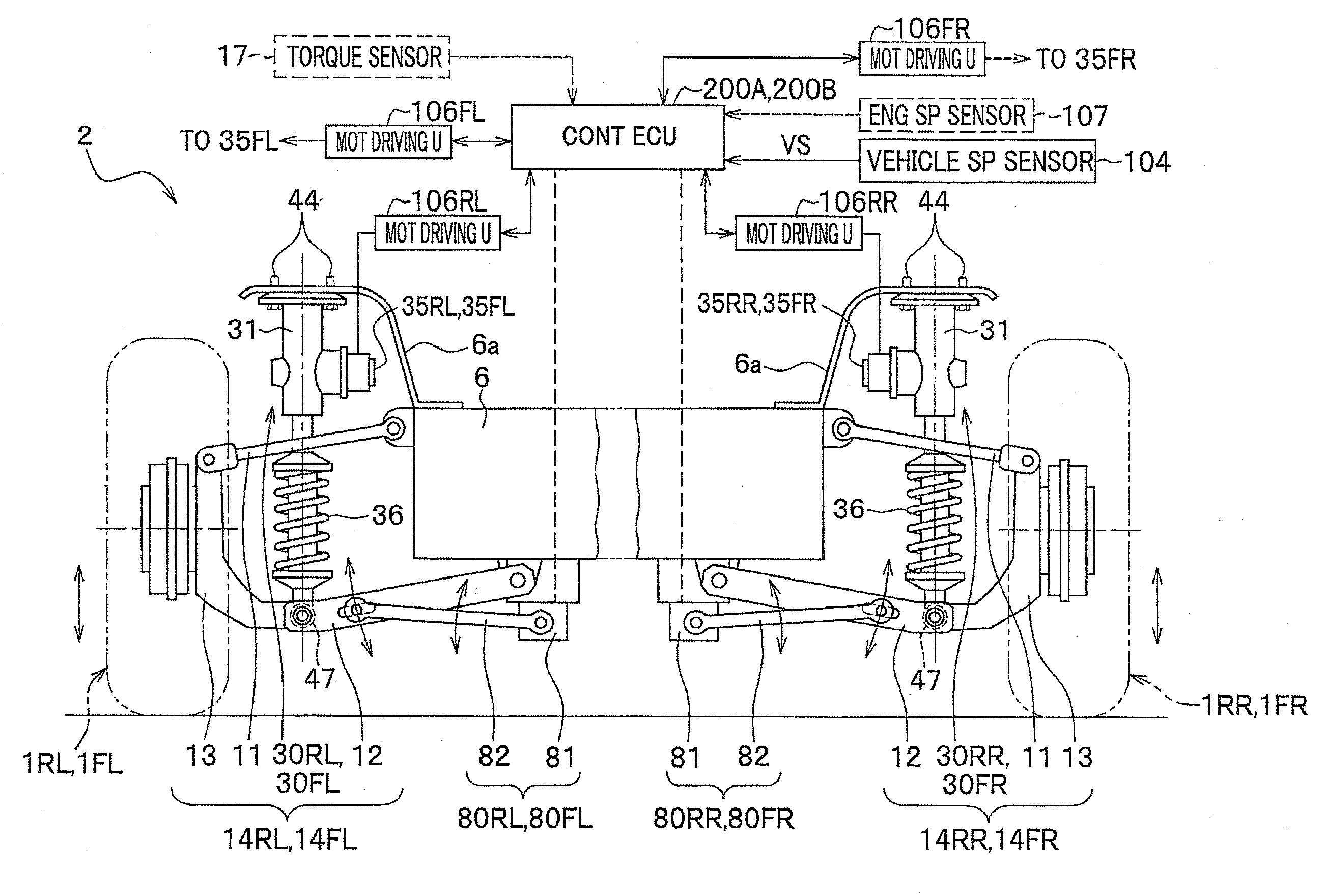
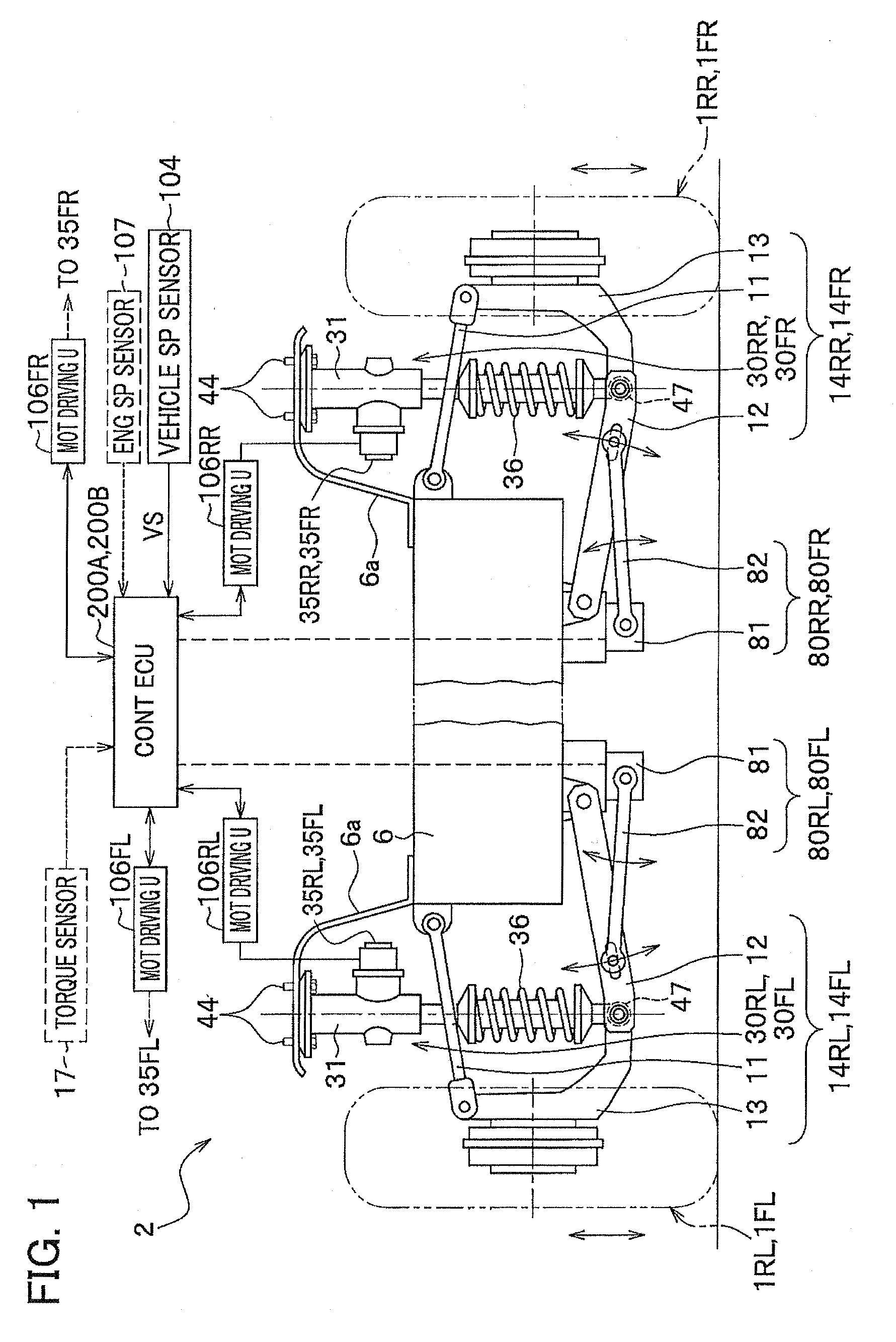
[0057]With reference to FIGS. 1 to 3, and also FIG. 5 will be described major components of an electric damper (motor-driven damper device) of the embodiment.

[0058]In the embodiment, an explanation will be given of an example case where all suspension devices 14FL, 14FR, 14RL, and 14 RR of right and left front wheels 1FL, 1FR and right and left rear wheels 1RL and 1RR have respective electric damper conversion mechanisms 30FL, 30FR, 30RL, and 30RR of electric dampers (motor-driven damper devices) 303 (see FIG. 5, denoted as 303FL, 303FR, 303RL, 303RR in the figure).

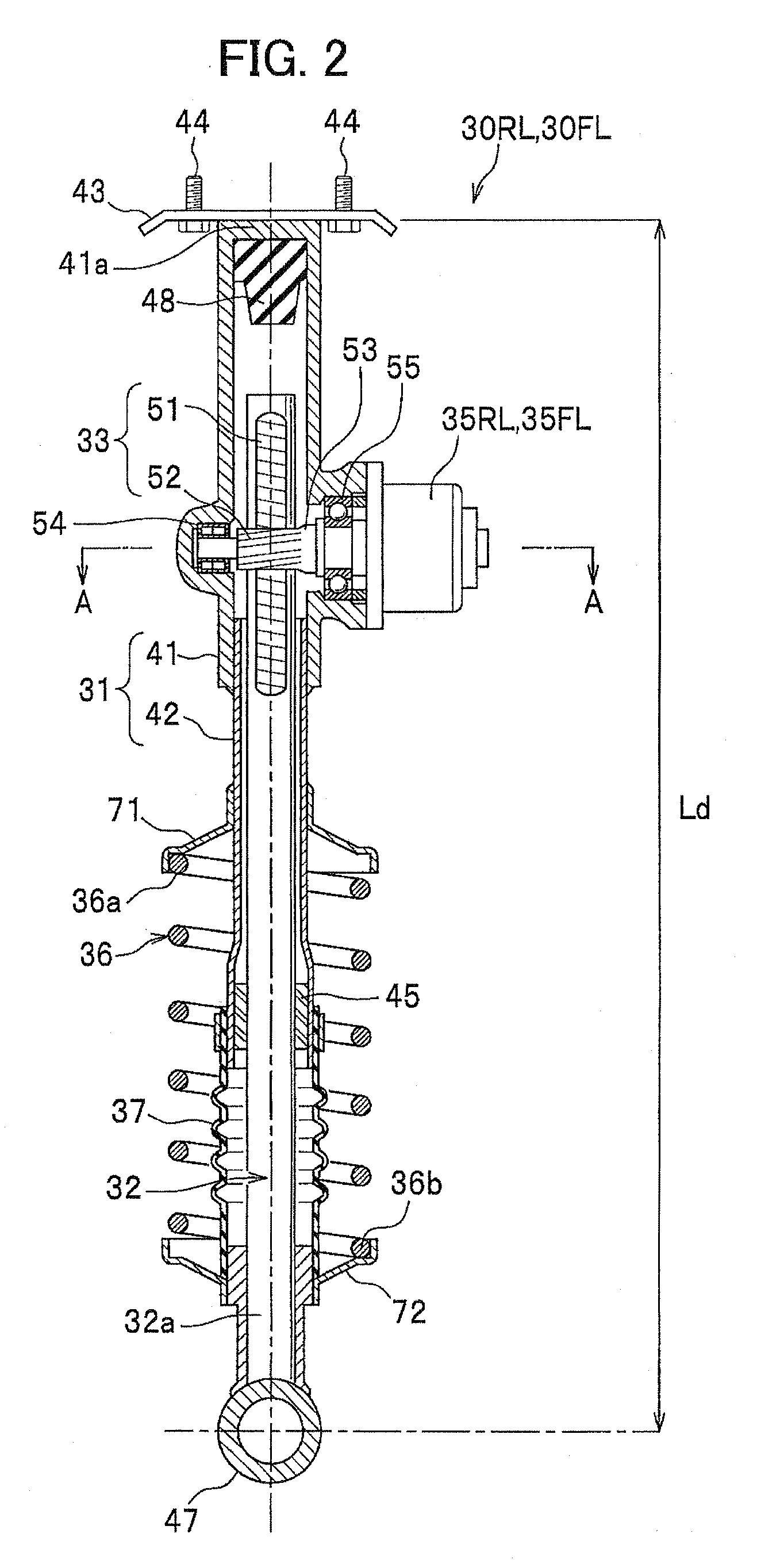
[0059]FIG. 1 is an exemplary diagram showing a vehicle having a vehicle suspension device equipped with an electric damper as viewed from the back. FIG. 2 is a cross-sectional view showing an electric damper conversion mechanism of an electric damper. FIG. 3 is a partial cross-sectional view along a line A-A in FIG. 2.

[0060]FIG. 1 shows a rear suspension, but since a front suspension generally has the same structure as th...

second embodiment

[0195]Next, with reference to FIGS. 15 to 20 and also FIG. 1 accordingly, an explanation will be given of an electric damper according to the second embodiment of the present invention.

[0196]In the second embodiment, a control ECU 200B has a control function of an electric power steering in addition to the functions of the control ECU 200A of the electric damper of the first embodiment. In the control ECU 200B, an output signal (steering wheel torque detection signal) from a torque sensor (steering wheel torque sensor) 17 is used for controlling the damping force of an electric damper.

[0197]The control ECU 200B also has a function as a “control device that controls an electric motor of an electric power steering device” recited in claims.

[0198]FIG. 15 is a layout drawing showing the major components of a vehicle in which an electric damper of the second embodiment of the present invention is combined with an electric power steering device.

[0199]The same structural components as thos...

third embodiment

[0231]Next, an explanation will be given of an electric damper according to the third embodiment of the present invention with reference to FIGS. 21 to 24.

[0232]The third embodiment is made based on the second embodiment, and the difference from the second embodiment is to acquire both frequency of unbalance wheel vibration and magnitude thereof from the component of the unbalance wheel vibration contained in a steering wheel torque detection signal ST output from the torque sensor 17.

[0233]In order to do so, as shown in FIG. 21, a control unit (damping unit) 210C has a power spectrum computation unit 212 and an unbalance wheel vibration detection unit (unbalance-wheel-vibration-frequency acquiring unit) 214, instead of the bandpass cutoff frequency setting units 211, 213, the bandpass filter computation unit 215, the power spectrum computation unit 217 and the frequency offset amount computation unit 219 in the second embodiment. Instead of the low-pass cutoff frequency setting uni...


PUM


Abstract

An electric damper which does not transmit unbalance wheel vibration to a vehicle body is provided. A low-pass cutoff frequency setting unit and a high-pass cutoff frequency setting unit respectively set the cutoff frequencies for band-stop filters to a frequency band corresponding to unbalance wheel vibration based on a signal indicating a vehicle speed from a vehicle speed sensor, and a function as a band-stop filter comprising a low-pass filter computation unit, a high-pass filter computation unit and an adder is computed for a displacement rate of the vertical motion of a wheel calculated by a differentiating unit in a damper control unit. A damper control amount computation unit calculates a control amount of controlling an electric motor for a motor-driven damper based on the calculated filtered displacement rate, and outputs a control signal to a motor driving unit through a driving circuit output unit.

Description

CROSS REFERENCE TO RELATED APPLICATIONS[0001]This application claims the foreign priority benefit under Title 35, United States Code, §119(a)-(d) of Japanese Patent Application No. 2008-053172, filed on Mar. 4, 2008 in the Japan Patent Office, the disclosure of which is herein incorporated by reference in its entirety.BACKGROUND OF THE INVENTION[0002]1. Field of the Invention[0003]The present invention relates to an electric damper for a vehicle suspension device.[0004]2. Description of the Related Art[0005]JP 2007-276571 A discloses a technology relating to an electric damper (motor-driven damper device) for a vehicle suspension device having a rack and pinion mechanism. Moreover, JP 2005-256921A discloses a technology of detecting a vertical acceleration parts on the spring of a vehicle using an acceleration sensor provided right above each wheel to detect the vertical acceleration, acquiring the power spectrum distribution of the vertical acceleration, reading out a power spectru...

Claims


Application Information

Patent Timeline
Patent Type & Authority Applications(United States)
IPC IPC(8): B60G13/00B60G13/18
CPCB60G17/06B60G2202/25F16F2232/04B60G2400/252B60G2500/104B60G2400/204B60G17/021B60G2202/42
Inventor YAMAWAKI, SHIGERUSHIMIZU, YASUOWATANABE, KATSUJIYONEDA, ATSUHIKO
Owner HONDA MOTOR CO LTD
Why Eureka
Try Eureka