
Beam Transport System and Method for Linear Accelerators

a technology of linear accelerators and beam transport systems, applied in linear accelerators, accelerators, electrical devices, etc., can solve the problems of limiting the use of beams, affecting beam quality and performance, and overall devices less than optimal for the intended use of accelerating charged particles, so as to achieve greater kinetic energy and kinetic energy

Inactive Publication Date: 2009-09-10
LAWRENCE LIVERMORE NAT SECURITY LLC
View PDF5 Cites 23 Cited by
  • Summary
  • Abstract
  • Description
  • Claims
  • Application Information

AI Technical Summary

Benefits of technology

[0018]Another aspect of the present invention includes a short pulse dielectric wall accelerator system comprising: a pulsed ion source for producing a bunch of charged particles; a dielectric wall beam tube surrounding an acceleration axis and having an inlet end and an outlet end; a plurality of pulse-forming lines transversely connected to and serially arranged along the dielectric wall beam tube, each pulse-forming line having a switch connectable to a high voltage potential for propagating at least one electrical wavefront(s) through the pulse-forming line independently from other pulse-forming lines to produce a short acceleration pulse adjacent a corresponding short axial length of the dielectric wall beam tube; a lens stack comprising two longitudinal compression electrodes, and at least one transverse focusing electrode(s), all of which are serially arranged along the acceleration axis between the pulsed ion source and the inlet end of the dielectric wall beam tube; voltage controller means for ramping in time a voltage difference produced between the two longitudinal compression electrodes so that upstream particles of the bunch have a greater kinetic energy than downstream particles so as to longitudinally compress the bunch of charged particles prior to being injected into the linear accelerator, and for controlling the voltages of the transverse focusing electrode(s) to control the transverse focusing of the bunch of charged partic

Problems solved by technology

The existing dielectric wall accelerators, such as the Carder DWA, however, have certain inherent problems which can affect beam quality and performance.
In particular, several problems exist in the disc-shaped geometry of the Carder DWA which make the overall device less than optimum for the intended use of accelerating charged particles.
Instead, a charged particle beam traversing the electric field created by such a structure will receive a time varying energy gain, which can prevent an accelerator system from properly transporting such beam, and making such beams of limited use.
The disc-shaped Blumlein structure of Carder can cause excessive levels of electrical energy to be stored in the system.
Such excess energy can have a detrimental effect on the performance and reliability of the overall device, which can lead to premature failure of the system.
This problem is further compounded when long acceleration pulses are required since the output pulse length of this disc-shaped Blumlein structure is directly related to the radial extent from the central hole.
As the preferred embodiment of initiating the switch is the use of a laser or other similar device, a highly complex distribution system is required.
Moreover, a long pulse structure requires large dielectric sheets for which fabrication is difficult.
This can also increase the weight of such a structure.
While some of the long pulse disadvantages can be alleviated by the use of spiral grooves in all three of the conductors in the asymmetric Blumlein, this can result in a destructive interference layer-to-layer coupling which can inhibit the operation.
Beam emittance makes beam transport in an accelerator challenging, especially in accelerators which employ time-varying energy waveforms to produce acceleration gradients (for example, RF standing wave linacs which produce energy waveforms having a sinusoidal time variation, or even short pulse dielectric wall accelerators in which due to a parasitic drain of energy from the pulse-forming lines the otherwise flattop pulse shape becomes distorted).
Variations in bunch length in particular can be problematic for capturing all the particles in a bunch if the bunch length is longer than the pulsewidth of the accelerating energy waveform.
While Einzel lens are frequently used at the injection end of tandem accelerators, they are considered not practical for beam handling and transport for high-energy applications except in very low-voltage accelerators.
Moreover, while Einzel lens have been used for transverse focusing, as known in the art, they have not been used for performing longitudinal bunch compression.

Method used


Image

  • Beam Transport System and Method for Linear Accelerators
  • Beam Transport System and Method for Linear Accelerators
  • Beam Transport System and Method for Linear Accelerators

Examples


Embodiment Construction

A. Compact Accelerator with Strip-Shaped Blumlein

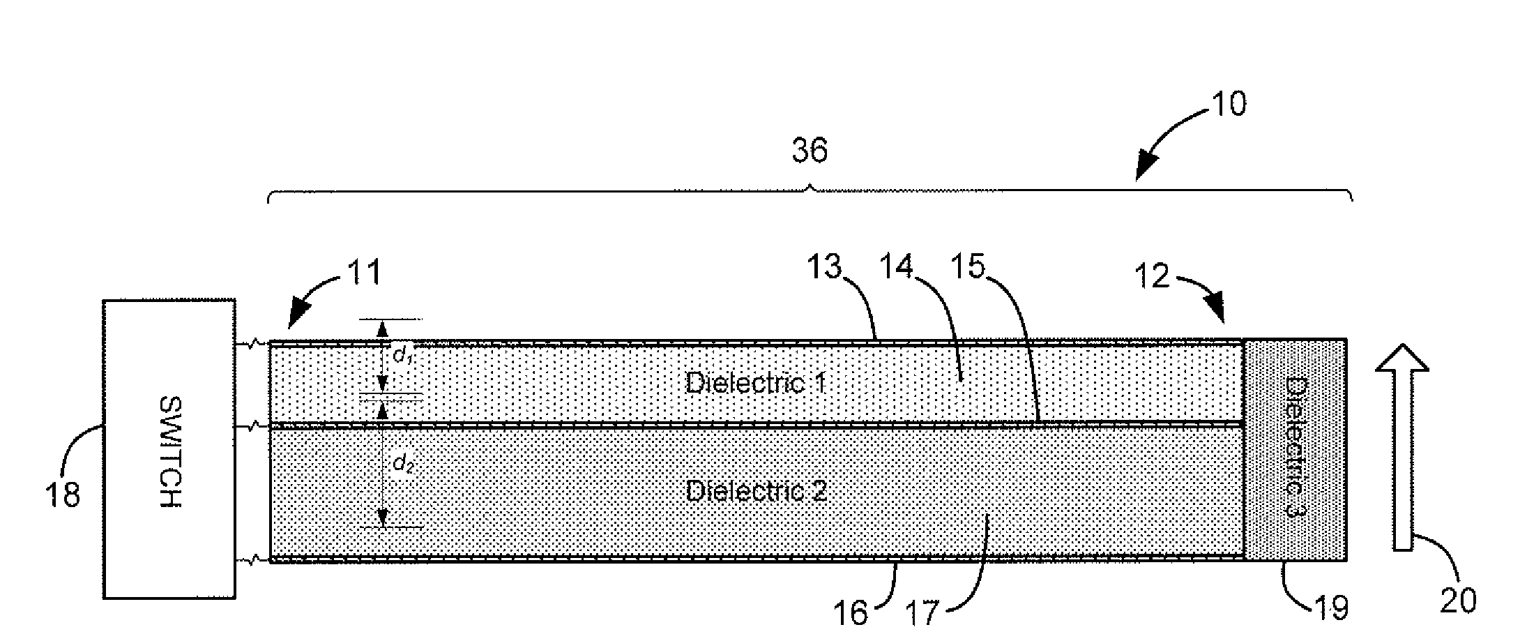
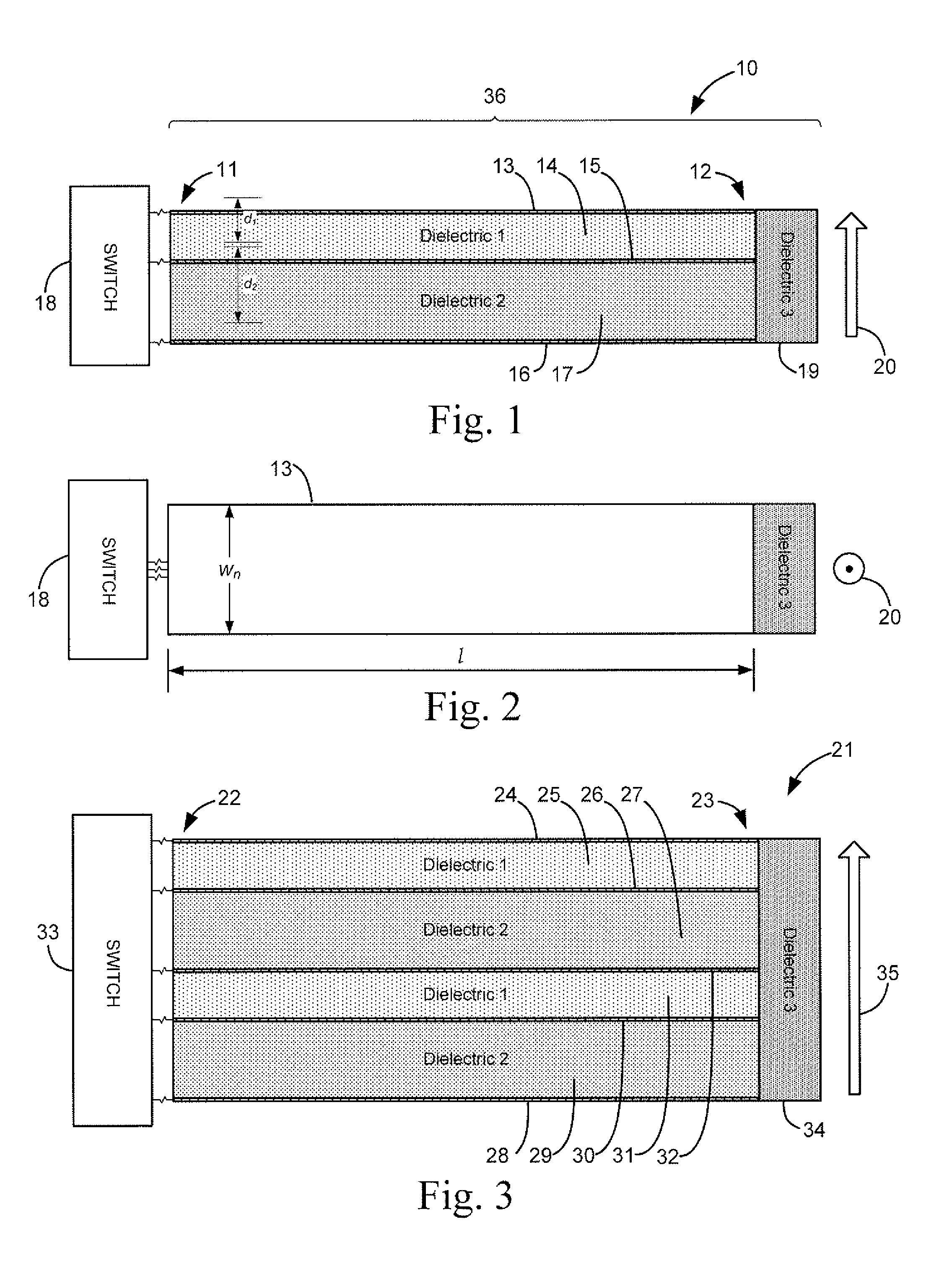
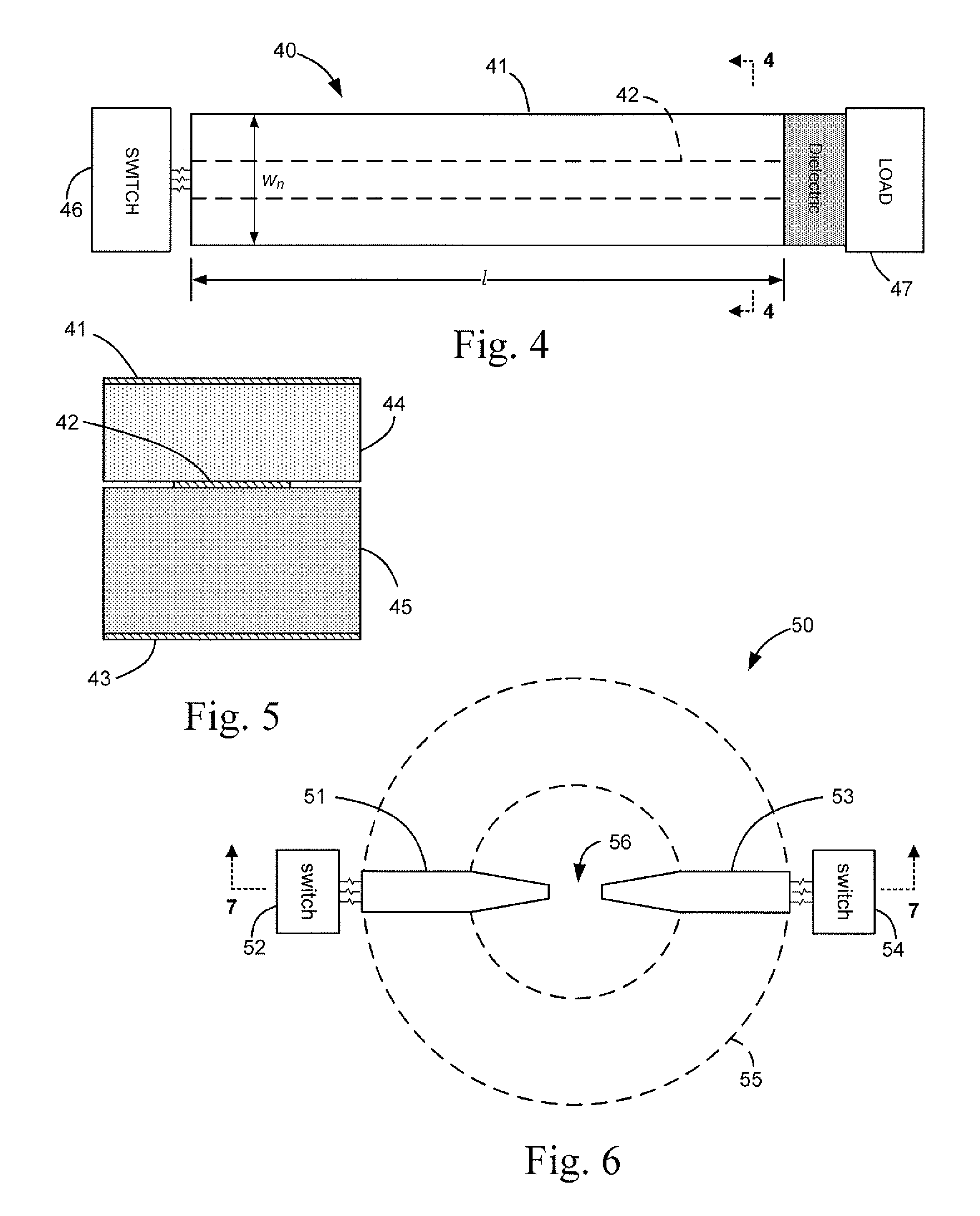
[0054]Turning now to the drawings, FIGS. 1-12 show a compact linear accelerator used in the present invention, having at least one strip-shaped Blumlein module which guides a propagating wavefront between first and second ends and controls the output pulse at the second end. Each Blumlein module has first second, and third planar conductor strips, with a first dielectric strip between the first and second conductor strips, and a second dielectric strip between the second and third conductor strips. Additionally, the compact linear accelerator includes a high voltage power supply connected to charge the second conductor strip to a high potential, and a switch for switching the high potential in the second conductor strip to at least one of the first and third conductor strips so as to initiate a propagating reverse polarity wavefront(s) in the corresponding dielectric strip(s).

[0055]The compact linear accelerator has at least one strip...


PUM


Abstract

A charged particle beam transport system and method for linear accelerators includes a lens stack having two electrodes serially arranged along an acceleration axis between a charged particle source, and a linear accelerator. After producing and extracting a bunch of charged particles (i.e. particle beam) from the particle source, a voltage difference between the two electrodes is ramped in time to longitudinally compress the particle beam to be shorter than the pulsewidth of acceleration pulses produced in the accelerator. Additional electrodes may be provided in the lens stack for performing transverse focusing of the charged particle bunch and controlling a final beam spot size independent of the current and energy of the particle beam. In a traveling wave accelerator embodiment having a plurality of independently switchable pulse-forming lines, beam transport can also be controlled by triggering multiple adjacent lines simultaneously so that the physical size of the accelerating electric field is longer than the charged particle bunch, as well as by controlling trigger timing of the pulse-forming lines to perform alternating phase focusing.

Description

CROSS-REFERENCE TO RELATED APPLICATIONS[0001]This application claims priority in U.S. Provisional Application No. 60 / 934,213 filed Jun. 11, 2007. This application is also a continuation-in-part of prior application Ser. No. 11 / 586,378, filed Oct. 24, 2006 which is a continuation-in-part of prior application Ser. No. 11 / 036,431, filed Jan. 14, 2005, which claims the benefit of U.S. Provisional Application No. 60 / 536,943, filed Jan. 15, 2004; and application Ser. No. 11 / 586,378 also claims the benefit of U.S. Provisional Application Nos. 60 / 730,128, 60 / 730,129, and 60 / 730,161, filed Oct. 24, 2005 and U.S. Provisional Application No, 60 / 798,016, filed May 4, 2006, all of which are incorporated by reference herein.FEDERALLY SPONSORED RESEARCH OR DEVELOPMENT[0002]The United States Government has rights in this invention pursuant to Contract No. DE-AC52-07NA27344 between the United States Department of Energy and Lawrence Livermore National Security, LLC for the operation of Lawrence Live...

Claims


Application Information

Patent Timeline
IPC IPC(8): H05H9/00
CPCH05H7/02H05H9/00
Inventor CHEN, YU-JIUANCAPORASO, GEORGE J.NELSON, SCOTT D.
Owner LAWRENCE LIVERMORE NAT SECURITY LLC
Learn More