Ac voltage output apparatus and hybrid vehicle including the same
a voltage output and hybrid technology, applied in the direction of dynamo-motor starters, dynamo-electric converter control, batteries/cells, etc., can solve the problem of not addressing such a problem, and achieve the effect of reducing cost, reducing weight, and small siz
- Summary
- Abstract
- Description
- Claims
- Application Information
AI Technical Summary
Benefits of technology
Problems solved by technology
Method used
Image
Examples
first embodiment
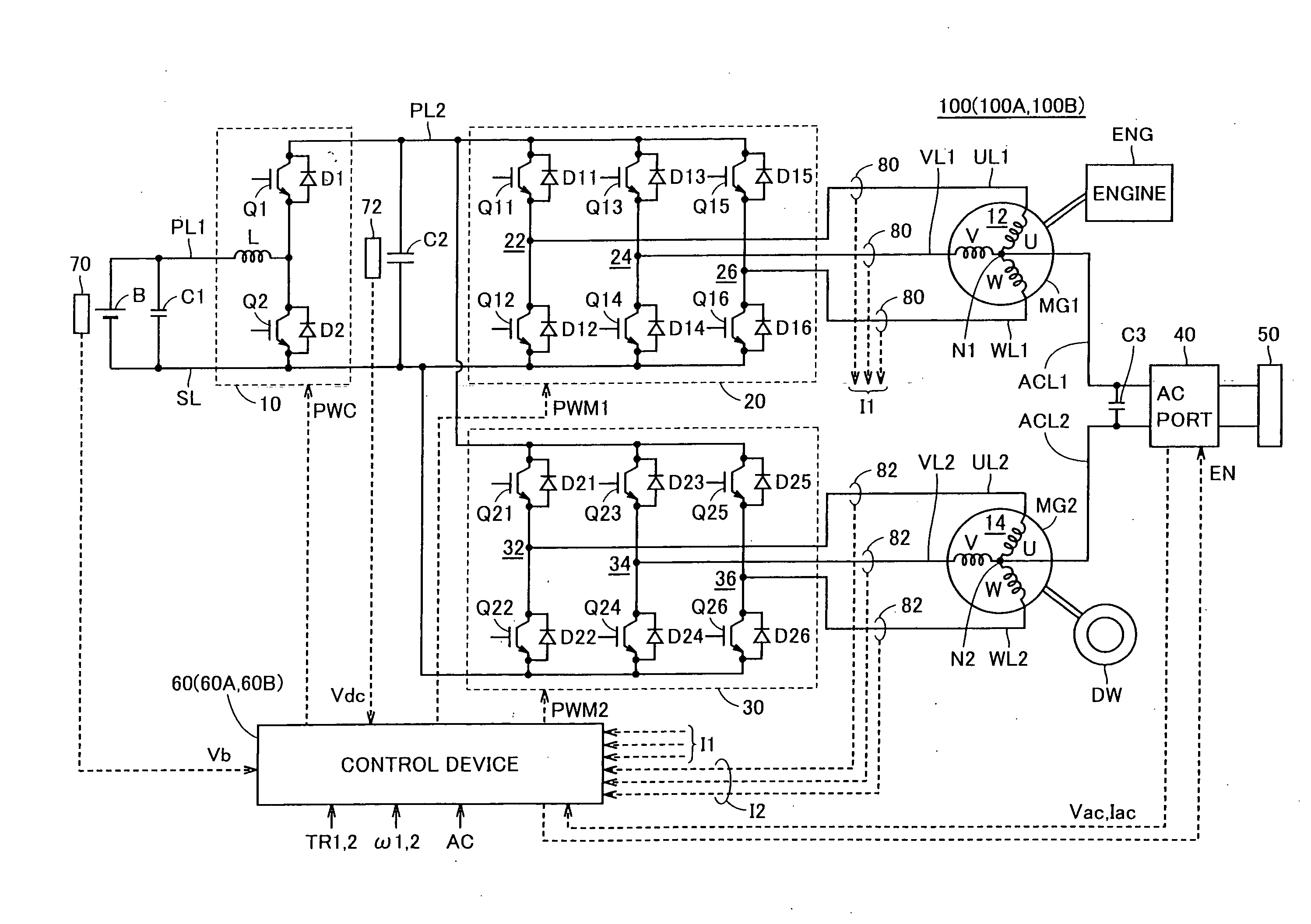
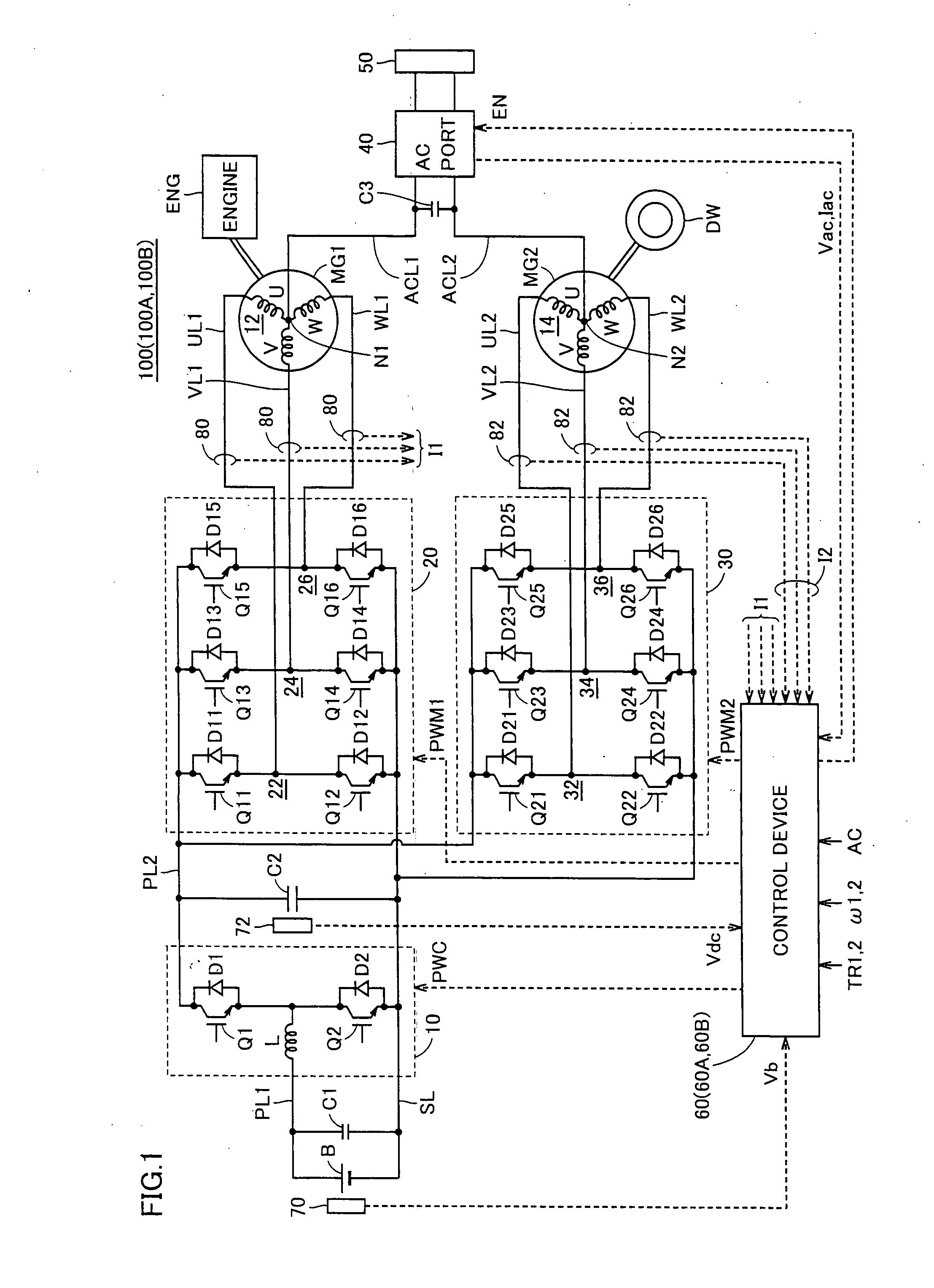
[0041]FIG. 1 is a block diagram showing an overall AC voltage output apparatus 100 according to a first embodiment of the present invention. Referring to FIG. 1, AC voltage output apparatus 100 includes a battery B, a boost converter 10, inverters 20, 30, motor-generators MG1, MG2, AC output lines ACL1, ACL2, an AC port 40, a connector 50, a control device 60, capacitors C1 to C3, power supply lines PL1, PL2, a ground line SL, U-phase lines UL1, UL2, V-phase lines VL1, VL2, W-phase lines WL1, WL2, voltage sensors 70, 72, and current sensors 80, 82.
[0042]AC voltage output apparatus 100 is mounted on a vehicle such as a hybrid vehicle. Motor-generator MG1 is incorporated in the hybrid vehicle as a component connected to an engine ENG and operating as a motor capable of starting engine ENG and as a generator driven by engine ENG. Motor-generator MG2 is incorporated in the hybrid vehicle as a motor connected to a drive wheel DW and driving drive wheel DW.
[0043]Battery B has a positive e...
second embodiment
[0103]FIG. 6 illustrates the output circuit outputting to the load device the commercial AC voltage generated across neutral points N1, N2 in AC voltage output apparatus 100 shown in FIG. 1. Referring to FIG. 6, in the output circuit, capacitor C3 is connected between AC output lines ACL1, ACL2. Capacitor C3 serves to eliminate influence of ripple to the load device (load R) connected to connector 50 through an outlet 55.
[0104]On the other hand, if capacitor C3 is provided, an LC circuit is formed by the coil of motor-generators MG1, MG2 and capacitor C3. As described so far, when motor-generator MG1 revolves, the harmonic of the counter-electromotive force appears in the potential of neutral point N1. Here, if a component having a frequency in the vicinity of the resonance frequency of the LC circuit is present in the harmonic component, the output circuit (LC circuit) resonates at the resonance frequency and the amplitude of the harmonic component having the frequency in the vicin...
third embodiment
[0124]In the first and second embodiments described above, generation of the commercial AC voltage is premised on a condition that the vehicle is stopped. In a third embodiment, the commercial AC voltage of which distortion is small can be generated and supplied to the load device even during running of the vehicle.
[0125]An AC voltage output apparatus 100B according to the third embodiment includes a control device 60B instead of control device 60 in the configuration of AC voltage output apparatus 100 according to the first embodiment shown in FIG. 1. Control device 60B includes a second inverter control unit 63A instead of second inverter control unit 63 in the configuration of control device 60 in the first embodiment shown in FIG. 2.
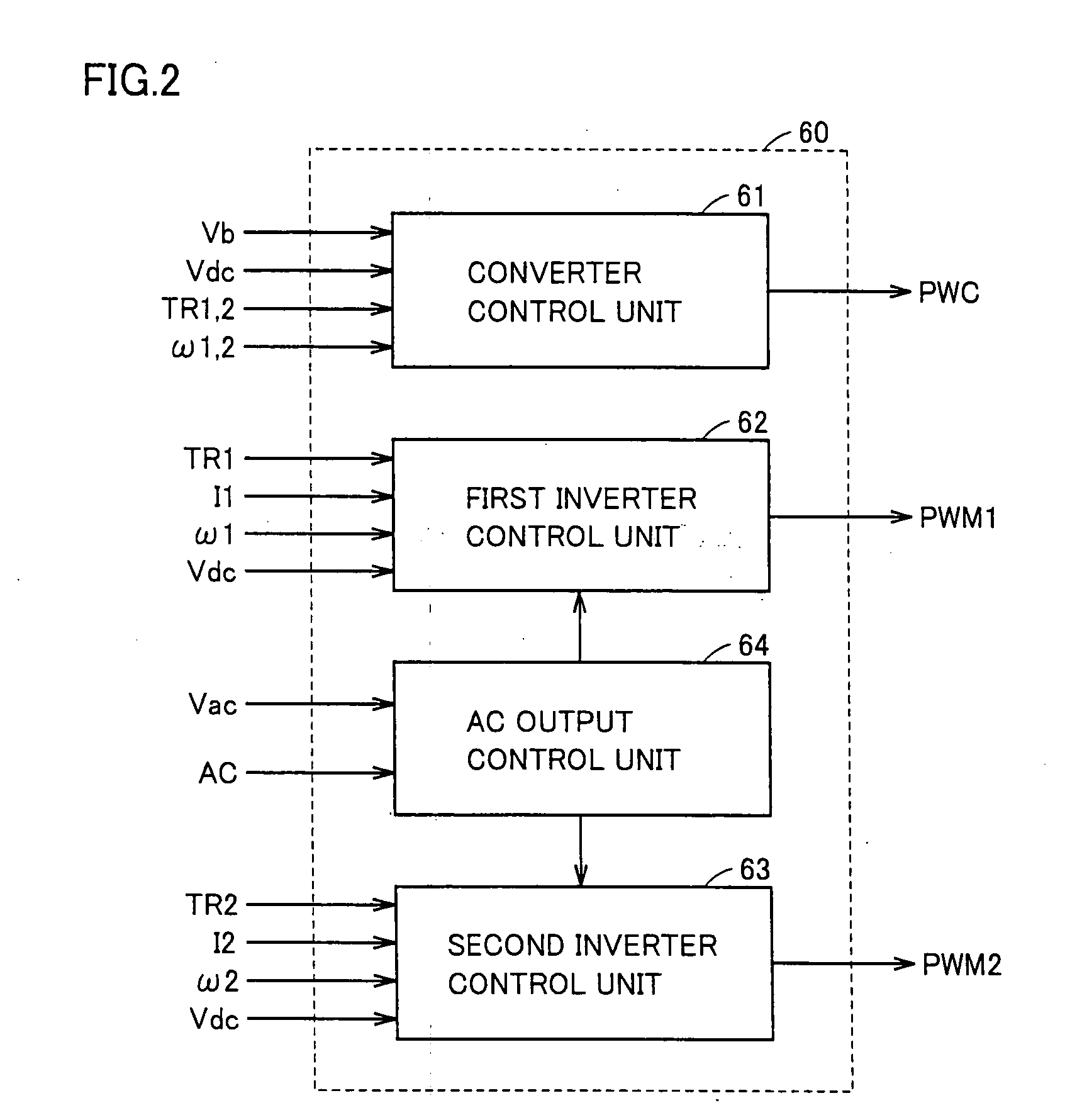
[0126]FIG. 10 is a functional block diagram showing in detail first and second inverter control units 62, 63A and AC output control unit 64 in the third embodiment of the present invention. Referring to FIG. 10, second inverter control unit 63A furth...
PUM
 Abstract
Description
Claims
Application Information
 - R&D
- Intellectual Property
- Life Sciences
- Materials
- Tech Scout
- Unparalleled Data Quality
- Higher Quality Content
- 60% Fewer Hallucinations
Browse by: Latest US Patents, China's latest patents, Technical Efficacy Thesaurus, Application Domain, Technology Topic, Popular Technical Reports.
© 2025 PatSnap. All rights reserved.Legal|Privacy policy|Modern Slavery Act Transparency Statement|Sitemap|About US| Contact US: help@patsnap.com


