Optoelectronic component and optical subassembly for optical communication

a technology of optical communication and optical subassembly, which is applied in the direction of electrical apparatus casings/cabinets/drawers, instruments, etc., can solve the problems of difficult to prevent the formation of thick films, the shape and thickness of thick films are not consistent, and the optical properties of products cannot be well controlled. , to achieve the effect of lowering the manufacturing cos

Inactive Publication Date: 2009-09-10
CORETEK OPTO CORP
View PDF2 Cites 22 Cited by
  • Summary
  • Abstract
  • Description
  • Claims
  • Application Information

AI Technical Summary

Benefits of technology

[0007]A housing of an optoelectronic component of the invention, especially a TO-can/leadframe housing, has an opening, and no glass or lens is located on the housing, so the manufacturing cost can be lowered. In addition, an optical coupling st...

Problems solved by technology

However, it is very difficult to prevent the formation of the thick film from having the thickness of several tens of micrometers, at least in general, if the frequently-used conventional glue (e.g., epoxy or silicone) is adop...

Method used


Image

  • Optoelectronic component and optical subassembly for optical communication
  • Optoelectronic component and optical subassembly for optical communication
  • Optoelectronic component and optical subassembly for optical communication

Examples


Embodiment Construction

[0072]The present invention will be apparent from the following detailed description, which proceeds with reference to the accompanying drawings, wherein the same references relate to the same elements.

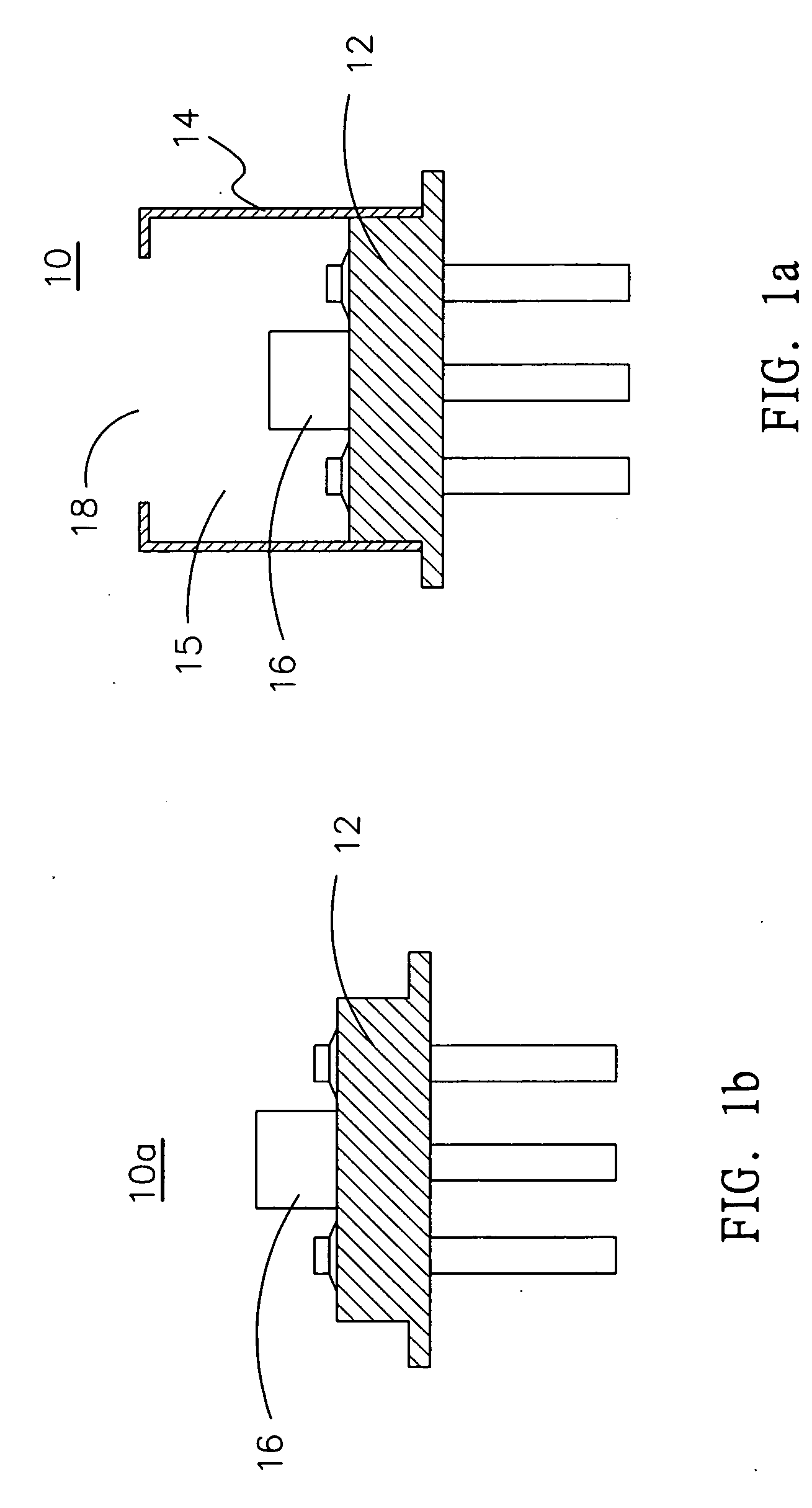
[0073]FIG. 1a shows an optoelectronic component 10 with the TO-can architecture. Referring to FIG. 1a, the optoelectronic component 10 has a metal header 12 and a metal housing 14, both can be combined into a single unit. A housing chamber 15 is formed inside the housing 14. An optoelectronic device 16 is mounted in the housing 14 and fixed to the header 12.

[0074]More particularly, one end of the housing 14 has an opening 18. The opening 18 is communicated with the housing chamber 15 and located opposite the optoelectronic device 16.

[0075]FIG. 1b shows an optoelectronic component 10a, in which no housing is disposed on the header 12, so the optoelectronic device 16 has an open periphery. In other words, the optoelectronic device 16 emits or receives light, which is similar to that of ...


PUM


Abstract

An optoelectronic component and an optical sub-assembly for optical communication. The optoelectronic component has a housing and one end formed with an opening. An optoelectronic device is located in the housing and faces the opening. A barrel is combined with the optoelectronic component to form the optical sub-assembly, and the barrel has a lens configuration facing the opening. The lens can enter the housing through the opening to approach the optoelectronic device. Thus, the manufacturing costs of the optoelectronic component and the optical sub-assembly can be lowered, and the optical coupling efficiency of the optical sub-assembly can be enhanced. In addition, a film covers the surface of the optoelectronic device to improve the device reliability.

Description

BACKGROUND OF THE INVENTION[0001]1. Field of Invention[0002]The invention relates to a component for optical communication, and more particularly to an optical sub-assembly composed of a barrel and an optoelectronic component, wherein the package types of the optoelectronic component include TO-can (TO Open Can) architecture and leadframe architecture, and the type of the barrel may be SC, ST, LC, or their individual pigtail architecture.[0003]2. Related Art[0004]The optical communication is to achieve the signal transmission effect via optical-to-electrical conversion. An optical sub-assembly (OSA) to be connected to an optical fiber connector has to be located at each of a signal transmitting end and a signal receiving end.[0005]U.S. Pat. No. 7,290,946 discloses an optical sub-assembly, which is composed of an optoelectronic component and a barrel combined together, in one of the examples thereof. A housing of the optoelectronic component is formed with an opening so that the effe...

Claims


Application Information

Patent Timeline
IPC IPC(8): G02B6/36H05K5/06H01S5/0232
CPCG02B6/4204G02B6/4212G02B6/4248H01S5/02212H01S5/0282H01S5/02244H01S5/02284H01S5/02288H01S5/0222H01L2224/48091H01L2224/73265H01S5/02253H01S5/02251H01S5/0232H01L2924/00014
Inventor YUANG, RONG-HENG
Owner CORETEK OPTO CORP
Why Eureka
Try Eureka