Biaxially Oriented Nanocomposite Film, Method of Manufacture, and Articles Thereof

a nanocomposite film and biaxial orientation technology, applied in the field of biaxial orientation nanocomposite film, methods of manufacture, can solve the problems of non-uniform distribution of filler, biaxial oriented composite film materials prepared by blown film methods from becoming commercially available in the market, and challenging biaxial stretching of composite polymeric materials into relatively thin films

Inactive Publication Date: 2009-09-10
GENERAL ELECTRIC CO
View PDF14 Cites 46 Cited by
  • Summary
  • Abstract
  • Description
  • Claims
  • Application Information

AI Technical Summary

Benefits of technology

[0008]In one embodiment, a method comprises mixing a nano-filler and a polymer composition to form a nanocomposite; extruding the nanocomposite as a melt through a spiral mandrel die to form a molten tube; expanding the tube biaxially by means of mechanical force and air pressure to form a bubble; and collapsing the bubble to form at least one sheet of a biaxially oriented nanocomposite film, wherein the biaxially oriented nanocomposite film has a breakdown strength of at least 300 V / micrometer.

Problems solved by technology

Whereas oriented un-filled polymer films (polymers containing no fillers) are commonly prepared by the biaxial stretching of the polymer in the horizontal and vertical directions using the so-called “blown film” process, the biaxial stretching of composite polymeric materials into relatively thin films using the blown film method has been challenging.
Non-uniform flow of the melt through the extruder circular die, instability of the bubble formed by the injection of air into the softened material, the sensitivity of the stretching process to the presence of impurities in the composite material and / or extruder-die system, and non-uniform distribution of the filler into the polymer matrix are some of the challenges that have prevented biaxially oriented composite film materials prepared by blown film methods from becoming commercially available in the market.
However, this adversely affects mechanical properties such as impact strength and ductility of the composite polymeric material.
It is known also that non-oriented, or even uniaxially oriented, unfilled polypropylene films in impregnated power capacitors catastrophically fail in accelerated life tests.

Method used


Image

  • Biaxially Oriented Nanocomposite Film, Method of Manufacture, and Articles Thereof
  • Biaxially Oriented Nanocomposite Film, Method of Manufacture, and Articles Thereof
  • Biaxially Oriented Nanocomposite Film, Method of Manufacture, and Articles Thereof

Examples


examples

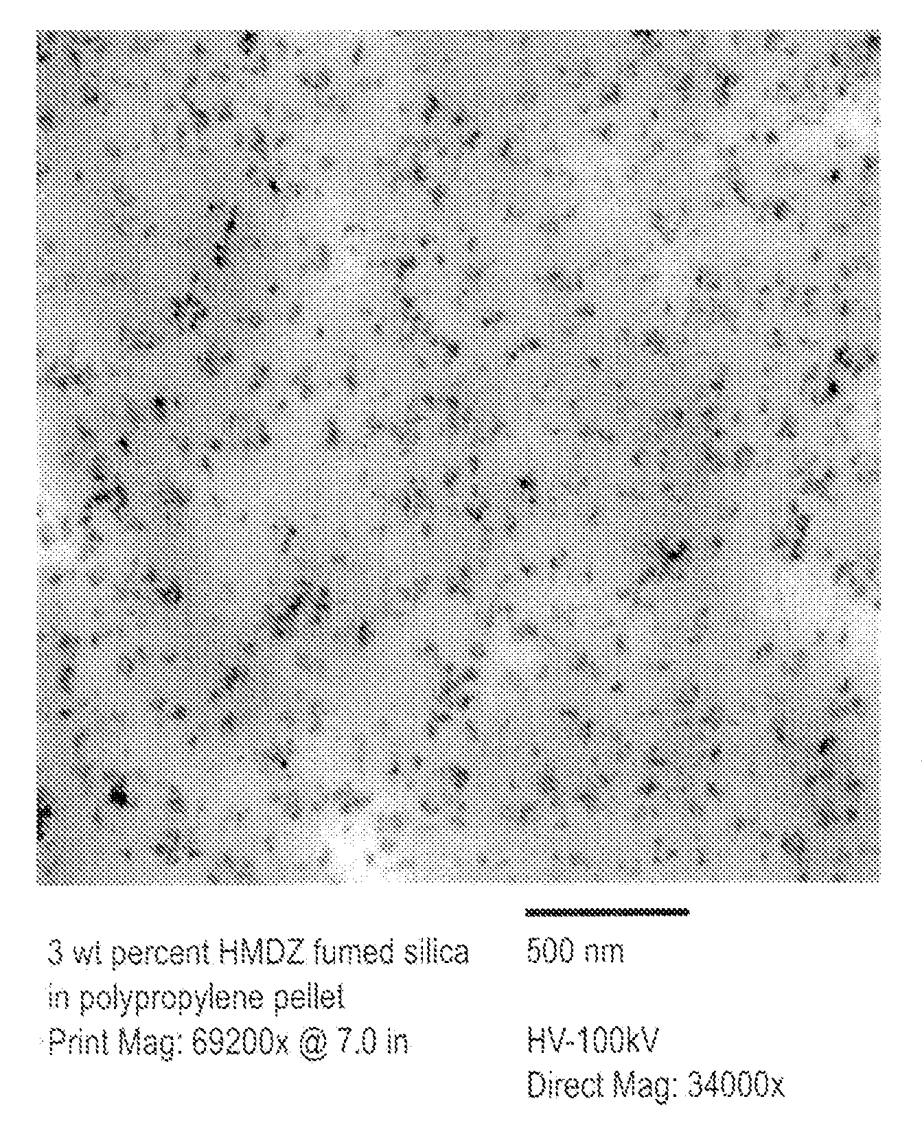
[0076]The following process was designed specifically for the incorporation of nano-fillers into thermoplastics (metering of components, melting of the polymer, dispersion of the filler into the melt). The extruder screw configuration maximizes mixing, minimizes viscous dissipation (low melt T, short residence time). It has been observed that under conditions of high melt temperature, high screw speeds, and long residence times, the molecular weight of polypropylene (PP) degrades rendering its viscosity too low for blown film applications. Polypropylene (PP), in the form of pellets, and nano-filler, a powder, were not pre-mixed, but added separately. PP and nano-filler were added to a twin-screw side feeder using two separate loss-in-weight feeders. PP and nano-filler were not dried prior to compounding (were used as received). The extruder barrel temperature was set at about 180-190° C. Two levels of filler were used: 3 and 6 weight percent (wt. % or wt %). Nano-fillers: Cabosil TS...

example c-1

to C-3 (09212006-1 to -3), Ex-1 and Ex-2 (09212006-4 to -5). Extrusion only experiment.

[0079]C-1 was a control sample of polypropylene used as received, run through the extruder.

[0080]In examples C-2, C-3, and Ex-1, polypropylene pellets and silica powder or alumina powder were fed into the side feeder separately using two loss-in-weight feeders at barrel two. A second atmospheric vent was located in barrel one.

[0081]In Ex-2 the polypropylene pellets were fed into barrel one and the nano-filler (silica) was fed into the side feeder at extruder barrel two. Otherwise, silica flowed out of the vent in barrel one when fed with polypropylene into the side feeder. One atmospheric vent was used at barrel eight.

[0082]The extruder conditions for C-1 to C-3 (09212006-1 to -3) and Ex-1 to Ex-2 (09212006-4 to -5) are listed in Tables 2A and 2B.

TABLE 2APolymerFillerDie MeltScrewDieFeed RateFeed RateTorqueTempSpeedPressureCondition #(kg / hr)(kg / hr)(%)(° C.)(rpm)(MPa)C-109212006-1220602125000.91C-2...

example ex-3 to ex-4.90.7

Example Ex-3 to Ex-4. 90.7 kg (200 pound) scale-up of Ex-1 and Ex-2. First and second extruders.

[0087]Polypropylene was added to barrel one and nano-filler was added to the extruder barrel two of a first extruder using two loss-in-weight feeders. One vent was used in barrel eight. The polypropylene was BORCLEAN from Borealis. The nano-filler was Cabosil TS530 HMDZ-treated fumed silica. The extruder ran for 4-6 hours with no interruption. Two levels of nano-filler were used: 3 and 6 wt % (weight percent) based on total weight of the nanocomposite. Six samples were taken from each one of the 90.7 kg (200 lb.) batches prepared using each silica level. The extruder settings for the 3 AVt % nanocomposite are shown in Table 4.

TABLE 4Ex-3. 3% silica, extruder conditions (six samples taken for one 200 lb batch)PolymerFillerDie MeltScrewDieActual BarrelFeed RateFeed RateTorqueTempSpeedpressureTemperaturesCondition #(kg / hr)(kg / hr)(%)(° C.)(rpm)(MPa)(° C.)10122006-122.10.72582155061.09150 / 189 / ...


PUM

PropertyMeasurementUnit
sizeaaaaaaaaaa
sizeaaaaaaaaaa
energy densityaaaaaaaaaa

Abstract

A method comprises mixing a nano-filler and a polymer composition to form a nanocomposite; extruding the nanocomposite as a melt through a spiral mandrel die to form a molten tube; expanding the tube biaxially by means of mechanical force and air pressure to form a bubble; and collapsing the bubble to form at least one sheet of a biaxially oriented nanocomposite film, wherein the biaxially oriented nanocomposite film has a breakdown strength of at least 300 V/micrometer.

Description

BACKGROUND OF THE INVENTION[0001]This disclosure relates to biaxially oriented nanocomposite films, methods of manufacture thereof, and articles comprising the same.[0002]Composite films containing a polymeric matrix and a filler stretched in the machine and cross-machine (transverse) directions are used in the manufacture of electronic articles, such as capacitors, sensors and batteries. The addition of small quantities of a filler having a large surface area to a polymer is intended to improve the dielectric properties of the film, such as breakdown strength and voltage endurance, among other properties. The stretching of films in two orthogonal directions is also known to improve the breakdown strength of the film compared to the non-oriented, or even uniaxially oriented film.[0003]Whereas oriented un-filled polymer films (polymers containing no fillers) are commonly prepared by the biaxial stretching of the polymer in the horizontal and vertical directions using the so-called “b...

Claims


Application Information

Patent Timeline
Patent Type & Authority Applications(United States)
IPC IPC(8): B32B27/20B29C49/08B29C70/00B29C48/04B29C48/05B29C48/10
CPCB29C47/0004Y10T428/259B29C47/0057B29C47/0059B29C47/20B29C47/28B29C47/38B29C47/402B29C47/404B29C70/58B29K2023/06B29K2023/12B29K2025/00B29K2027/16B29K2029/04B29K2059/00B29K2067/00B29K2069/00B29K2071/00B29K2075/00B29K2075/02B29K2077/00B29K2077/10B29K2081/06B29K2105/0008B29K2105/0026B29K2105/0032B29K2105/0038B29K2105/0044B29K2105/005B29K2105/06B29K2105/162B29K2105/256B29L2031/755H01G4/206H05K1/0373H05K1/0393H05K2201/0129H05K2201/0209H05K2201/0257B29C47/0026B29C48/022B29C48/10B29C48/0018B29C48/0019B29C48/32B29C48/34B29C48/395B29C48/402B29C48/404Y10T428/31645Y10T428/3154Y10T428/31721Y10T428/31504Y10T428/31786Y10T428/31855Y10T428/31551Y10T428/31533Y10T428/31507Y10T428/31725B29B7/483B29B7/489B29C48/04B29C48/05
Inventor SILVI, NORBERTOGIAMMATTEI, MARKIRWIN, PATRICIA CHAPMANCAO, YANGTAN, DANIEL QIMEAD, CHARLES
Owner GENERAL ELECTRIC CO
Why Eureka
Try Eureka