Cerebral perfusion monitor

a perfusion monitor and cerebral technology, applied in the field of measuring blood flow in the head, can solve the problems of increased blood flow to the brain, brain cell death, brain cell damage, etc., and achieve the effect of reducing noise or artifacts

Inactive Publication Date: 2009-09-10
ORSAN MEDICAL TECH
View PDF16 Cites 22 Cited by
  • Summary
  • Abstract
  • Description
  • Claims
  • Application Information

AI Technical Summary

Benefits of technology

[0034]d) performing data processing on one or more of the IPG signal, the PPG signal, and the cerebral blood flow indicator, to reduce noise or artifacts or both.

Problems solved by technology

There is a need to measure cerebral blood flow during various medical events and procedures, because any disturbance to the flow of blood to the brain may cause injury to the function of the brain cells, and even death of brain cells if the disturbance is prolonged.
A sudden increase in blood flow to the brain may also cause severe damage, and is especially likely to occur in newborn or premature babies, although such an increase may also occur in other patients with certain medical conditions, or during surgery.
But due to the different relation between blood pressure and cerebral blood flow in different medical conditions, there may be situations in which cerebral blood flow is inadequate even when blood pressure appears to be adequate.
Existing means for measuring cerebral blood flow are complex, expensive, and in some cases invasive, which limits their usefulness.
Three methods that are presently used only in research are 1) injecting radioactive xenon into the cervical carotid arteries and observing the radiation it emits as it spreads throughout the brain; 2) positron emission tomography, also based on the injection of radioactive material; and 3) magnetic resonance angiography, performed using a room-sized, expensive, magnetic resonance imaging system, and requiring several minutes to give results.
These three methods can only be carried out in a hospital or other center that has the specialized equipment available, and even in a hospital setting it is not practical to monitor patients continuously using these methods.
However, TCD fails to give a correct determination of blood flow in about 15% of patients, due to the difficulty of passing sound waves through the cranium, and it requires great skill by professionals who have undergone prolonged training and practice in performing the test and deciphering the results.
Another disadvantage of TCD is that it measures only regional blood flow in the brain, and does not measure global blood flow.
Blood flow through the vertebral arteries is difficult to measure by ultrasound because of their proximity to the vertebrae.

Method used


Image

  • Cerebral perfusion monitor
  • Cerebral perfusion monitor
  • Cerebral perfusion monitor

Examples


Embodiment Construction

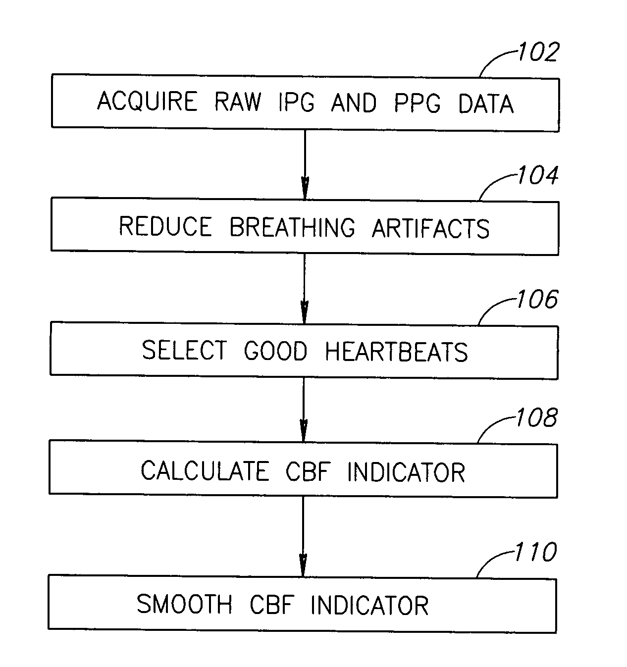
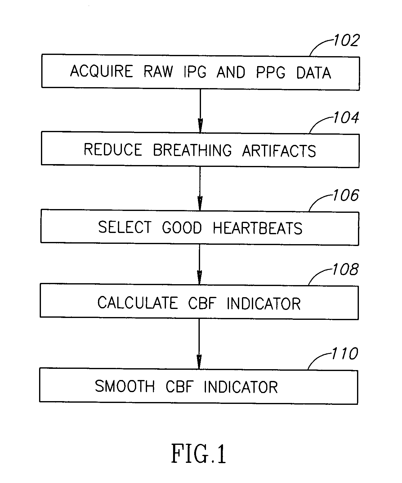
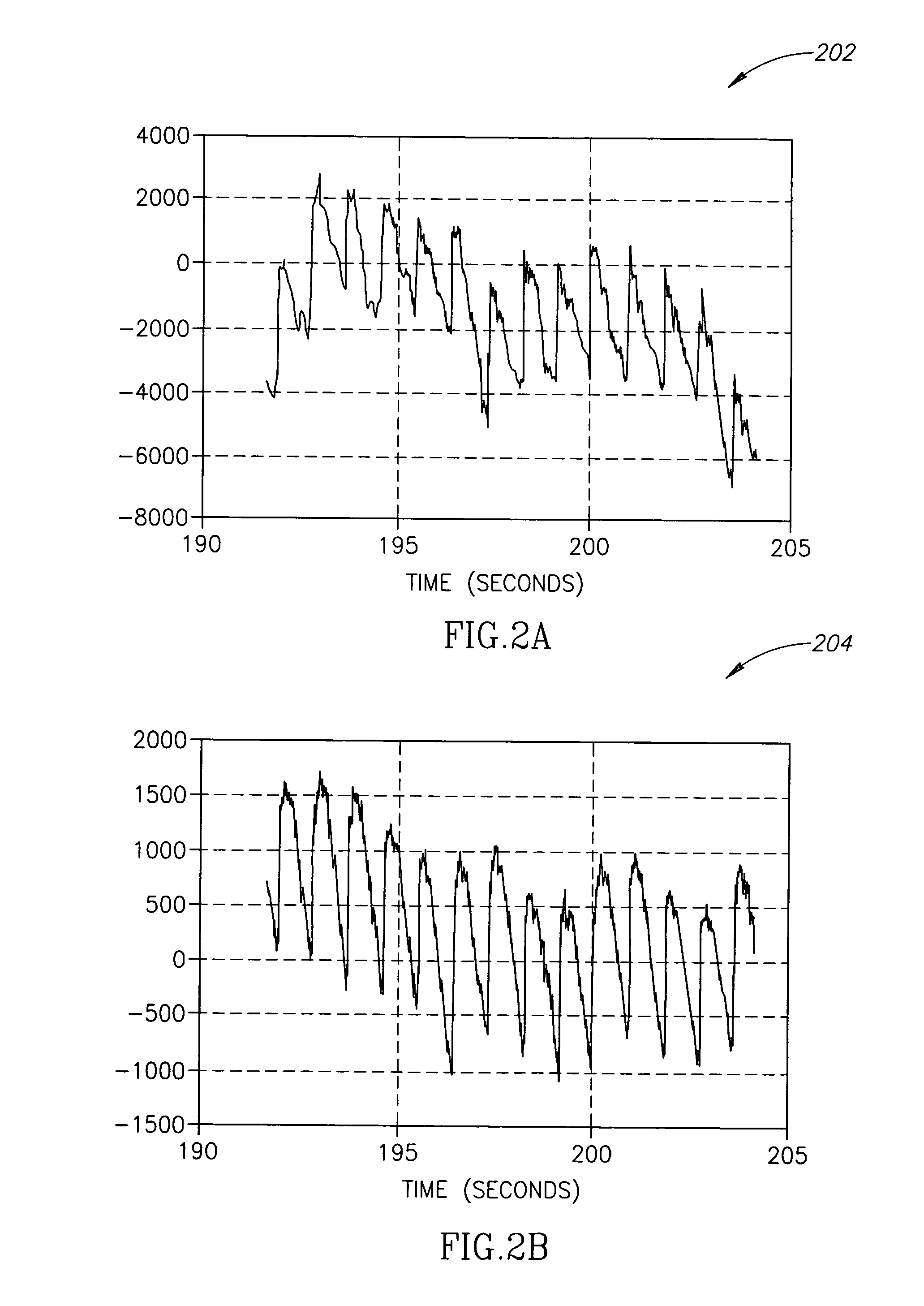
[0055]FIG. 1 shows a flowchart 100, outlining a method for finding cerebral blood flow (CBF) according to an exemplary embodiment of the invention. The different steps in flowchart 100 will be described with reference to graphs of data, shown in FIGS. 2, 3, and 4.

[0056]At 102, raw IPG and PPG data of the head is acquired. The data is acquired, for example, using any of the methods described in any of the above mentioned related patent applications or the patents, and publications as referenced in the Background, or any other methods known in the art for acquiring IPG and PPG data of the head. For example, combined sensors, incorporating both electrodes for IPG and optical sensors for PPG, are used, or separate sensors are used. Optionally, the IPG electrodes are designed to be of a size and shape, and are positioned on the head, so as to obtain IPG data that is relatively more sensitive to the impedance of the interior of the skull, and relatively less sensitive to the impedance of ...


PUM


Abstract

A method of estimating cerebral blood flow by analyzing IPG and PPG signals of the head, the method comprising:a) finding a maximum slope or most negative slope or the IPG signal, within at least a portion of the cardiac cycle;b) finding a maximum slope or most negative slope of the PPG signal, within at least a portion of the cardiac cycle;c) finding a ratio of the maximum or most negative slope of the IPG signal to the maximum or most negative slope of the PPG signal; andd) calculating a cerebral blood flow indicator from the ratio.

Description

RELATED APPLICATIONS[0001]The present application claims priority from, and is a continuation-in-part of two related PCT patent applications PCT / IL2005 / 000631 and PCT / IL2005 / 000632, both filed Jun. 15, 2005. Those PCT applications are both continuations-in-part of U.S. patent application Ser. No. 10 / 893,570, filed Jul. 15, 2004, which is a continuation-in-part of PCT patent application PCT / IL03 / 00042, filed Jan. 15, 2003, which claims benefit under 35 USC 119(e) from U.S. provisional patent application 60 / 348,278, filed Jan. 15, 2002. The disclosures of all of these applications are incorporated herein by reference.FIELD OF THE INVENTION[0002]The field of the invention relates to measuring blood flow in the head.BACKGROUND OF THE INVENTION[0003]There is a need to measure cerebral blood flow during various medical events and procedures, because any disturbance to the flow of blood to the brain may cause injury to the function of the brain cells, and even death of brain cells if the d...

Claims


Application Information

Patent Timeline
Patent Type & Authority Applications(United States)
IPC IPC(8): A61B5/026A61B5/053A61B5/0265A61B5/296
CPCA61B5/0261A61B5/0265A61B5/04008A61B5/0295A61B5/6814A61B5/6817A61B2562/164A61B5/0535A61B5/245
Inventor REICHMAN, YOSEFPOUPKO, BEN ZIONBEN-ARI, SHLOMI
Owner ORSAN MEDICAL TECH
Why Eureka
Try Eureka