Powder spray coating discharge assembly

a technology of spray coating and discharge assembly, which is applied in the direction of spraying power supply, electrostatic spraying apparatus, coating, etc., can solve the problems of difficult coating of the inside of such recesses, holes and craters in finished and cured powder films, faraday cages, etc., and achieves the effect of reducing the discharge current and increasing the conductivity of air

Inactive Publication Date: 2009-09-17
YU TUNG INVESTMENT HLDG
View PDF3 Cites 31 Cited by
  • Summary
  • Abstract
  • Description
  • Claims
  • Application Information

AI Technical Summary

Benefits of technology

[0049]The powder spray discharge coating assembly according to the fourth aspect of the invention automatically adjusts the discharge voltage and / or current at the discharge and / or counter electrode. Since higher powder quantities / throughputs have the effect of suppressing the corona discharge, a higher voltage for the same electrostatic energy would preferably be applied to the discharge and / or counter electrode. Different powder types may require different discharge voltages and / or currents to achieve sufficient charging, depending on the surface area / powder particle, the powder material, surface roughness etc. Thus, the discharge voltage and / or current is preferably adjustable to compensate for these variations. As the discharge or counter electrode degrades with use (e.g. by wear, attrition, oxidation, thermal cycling etc.) the applied discharge voltage and / or current is preferably automatically adjusted to compensate. Atmospheric conditions, such as temperature, humidity etc may affect the powder charging (e.g. higher humidity will lead to a reduced discharge current for a given discharge voltage since the conductivity of the air will be increased). Accordingly, it is a preferred feature of the invention that the discharge voltage and / or current be adjustable, preferably automatically, to compensate for these variations.

Problems solved by technology

There are 3 commonly recognized drawbacks with this method of charging, namely “Faraday cages”, “back ionisation” and “orange peel”.
These lines of force can be beneficial to create a wrap around effect and coat areas of the product which face away from the spray gun e.g. back surfaces, but they can cause a problem when coating into recesses as the lines of force are established to the outer edges of recesses and will not penetrate inside.
This can make it very difficult to coat the inside of such recesses.
Back ionisation is where the excess charge from the ionized air is entrapped into the powder layer deposited onto the surface of the product, and as the charge is all of the same polarity, repulsion effects can cause charge concentrations particularly in thicker coatings, which can erupt from the deposited powder layer to leave holes and craters in the finished and cured powder film.
In summary, the known arrangement has the disadvantage that that the nature, i.e. the strength and distribution, of the field depends largely on the geometry of the workpiece and the proximity of the discharge electrode to the workpiece.
The field lines are also established strongly between the discharge electrode and the external edges of recesses thus creating “Faraday Cages” within the recesses which are notoriously difficult to coat as the field is weak or non existent within deep recesses.
This is not very practical on a busy production line.
Although this can be useful, most products do not fall simply into one category and to change presets while spraying one part or between many different parts is also not very practical.
It is, however very difficult to prevent the counter electrode from becoming contaminated with powder and therefore ineffective after a short while.
In general the charging of the powder is slower and less efficient.
Another drawback with this method is that the discharge current is usually very high, typically around 100 μA which can cause powder to fuse onto the corona discharge needle due to the hot corona “glow” at the discharge point, this will reduce the charging efficiency and can lead to sparking due to capacitive discharge.
Another problem with running maximum Discharge voltage and current continuously is that more consideration must be given to the reliability of the highly stressed high voltage components and also the heat generated by the electronic parts of the spray gun.

Method used


Image

  • Powder spray coating discharge assembly
  • Powder spray coating discharge assembly
  • Powder spray coating discharge assembly

Examples


Embodiment Construction

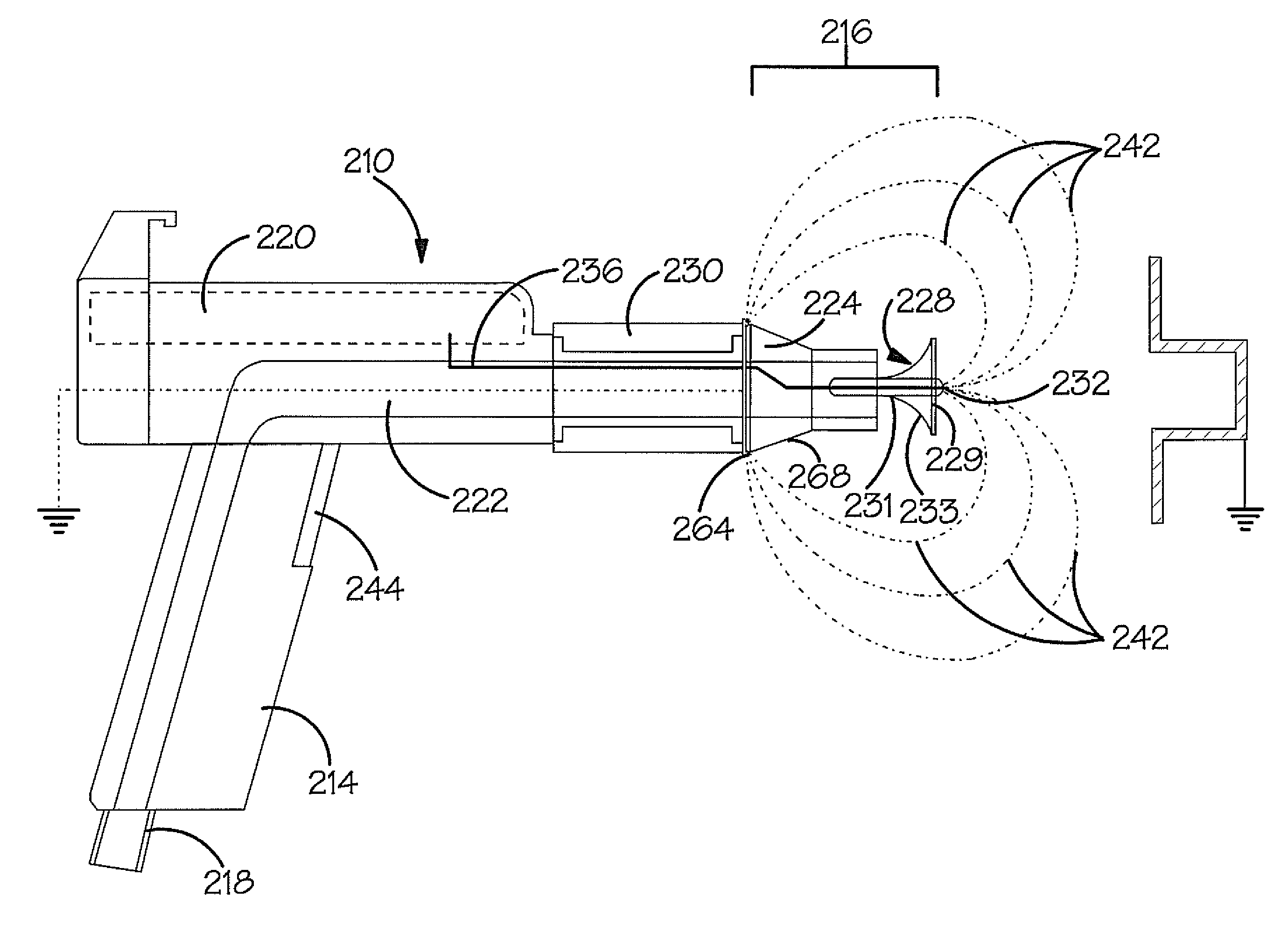
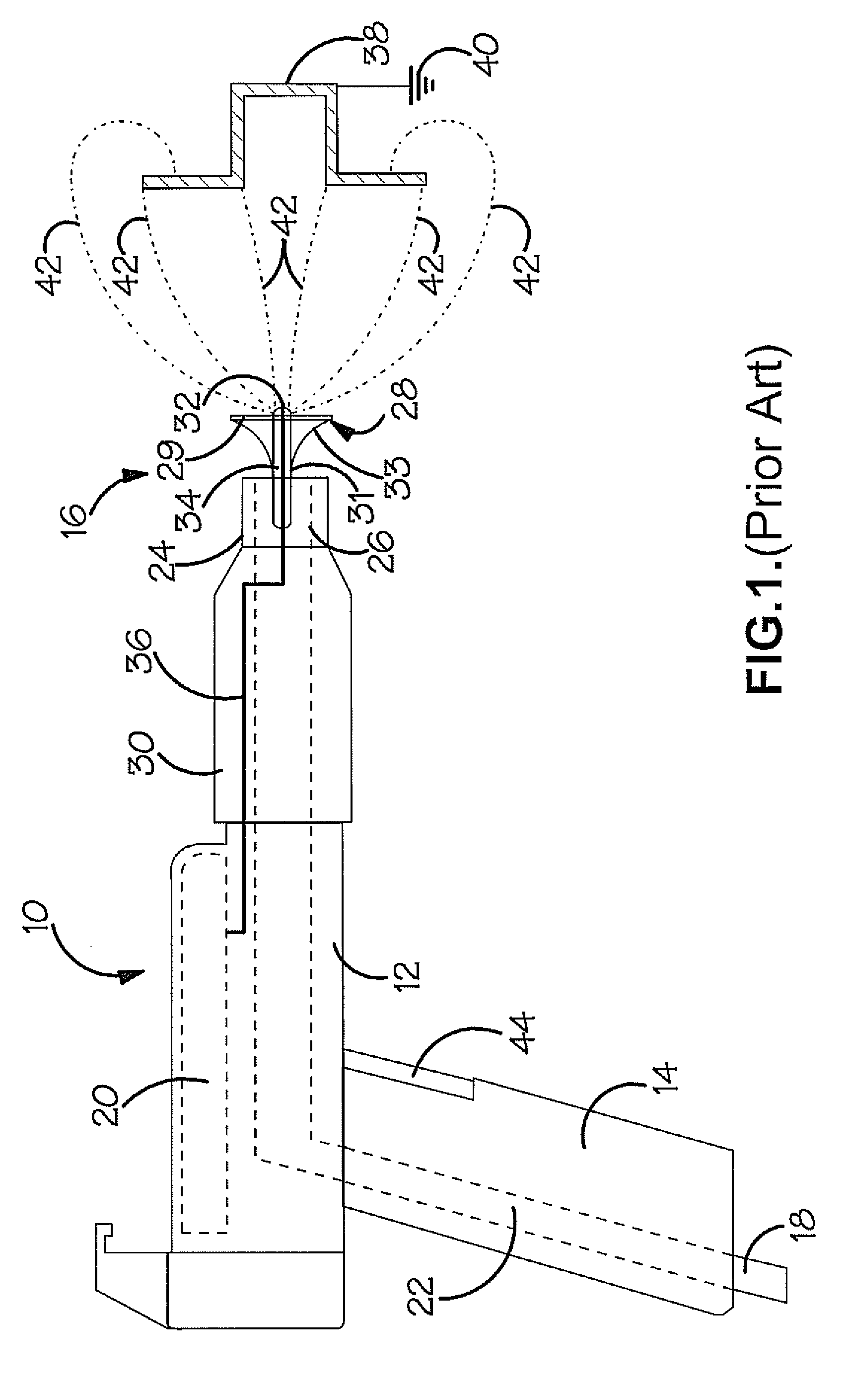
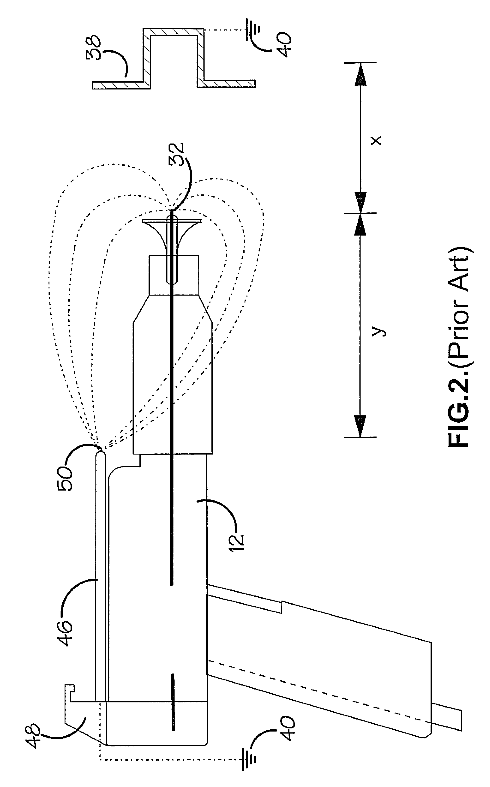
[0061]A prior art electrostatic powder spray gun 10 is shown in FIG. 1, which generally comprises a body 12, a grip 14 and a nozzle 16. At the bottom of the grip 14, there is a connector 18 for connecting the gun 10 to a hose (not shown) that supplies powder thereto and to a mains power supply. An upper part of the body 12 houses a power supply unit 20, which outputs a high voltage (positive or negative) from the incoming electrical power. Inside the body 10, a conduit 22 internally connects the hose connector 18 to the nozzle 16.

[0062]Interposed between the nozzle 16 and the body 12 is an electrically insulating annular spacing sleeve 30, known as a “nozzle nut”. The spacing sleeve 30 is detachable from the body 12.

[0063]The nozzle 16 comprises an annular plastics sleeve portion 24, whose aperture 26 is aligned with an end of the conduit 22. Concentrically aligned with, and protruding partially into, the aperture 26 is a deflector 28. The deflector 28 has a generally flat, circular...


PUM


Abstract

A powder spray coating discharge assembly (230, 260, 216, 228, 232) for connection to an electrostatic spray coating gun (210), the gun (210) having a gun body (212), means for connecting to a supply of coating powder and means for supplying a voltage (20) at first and second potentials respectively to first (292) and second electrical connections (294) each for connection to a respective one of a discharge electrode (232) and a counter electrode (260), the means for supplying the voltage (20) comprising: a variable voltage power supply (114) having an input connected to an electrical power source (110), an output connected to each of the first and second electrical connections (292, 294), a control circuit (128) for controlling the variable voltage power supply (20) and means (120) for sensing an output load, wherein the control circuit (128) is adapted to adjust the variable voltage power supply (20) to reduce the voltage and current in proportion to a sensed increase in load, or vice-versa.

Description

CROSS REFERENCE TO RELATED APPLICATION[0001]This application is a National Stage entry of International Application No. PCT / GB2007 / 050518, filed Aug. 31, 2007, the entire specification, claims and drawings of which are incorporated herewith by reference.BACKGROUND[0002]1. Field of the Invention[0003]This invention relates to electrostatic powder spray coating apparatus, and in particular, but not exclusively, to electrode arrangements for electrostatic powder spray coating apparatus.[0004]2. Introduction[0005]Electrostatic powder spray coating apparatus can be used for depositing powder coatings on substrates. A known electrostatic powder spray coating apparatus generally comprises a nozzle through which powder can be sprayed and a discharge electrode located adjacent to the nozzle. The discharge electrode is maintained at an elevated electrical potential with respect to a grounded workpiece so that an electromagnetic field is created between the discharge electrode and the workpiec...

Claims


Application Information

Patent Timeline
Patent Type & Authority Applications(United States)
IPC IPC(8): B05B5/025
CPCB05B5/032B05B5/0531B05B5/10B05B5/08B05B5/0533B05B5/025B05B5/053B05D1/04B05D1/06
Inventor KO, MAN KIN MICKEY
Owner YU TUNG INVESTMENT HLDG
Why Eureka
Try Eureka