
Solar servo control tracking device

a tracking device and solar energy technology, applied in solar heat collector controllers, optical radiation measurement, navigation instruments, etc., can solve the problems of large error range, large cost increase, and difficulty in detecting solar azimuth by tracking devices in power stations, so as to reduce the cost and improve the efficiency of solar energy generation

Active Publication Date: 2009-09-17
SDN
View PDF10 Cites 40 Cited by
  • Summary
  • Abstract
  • Description
  • Claims
  • Application Information

AI Technical Summary

Benefits of technology

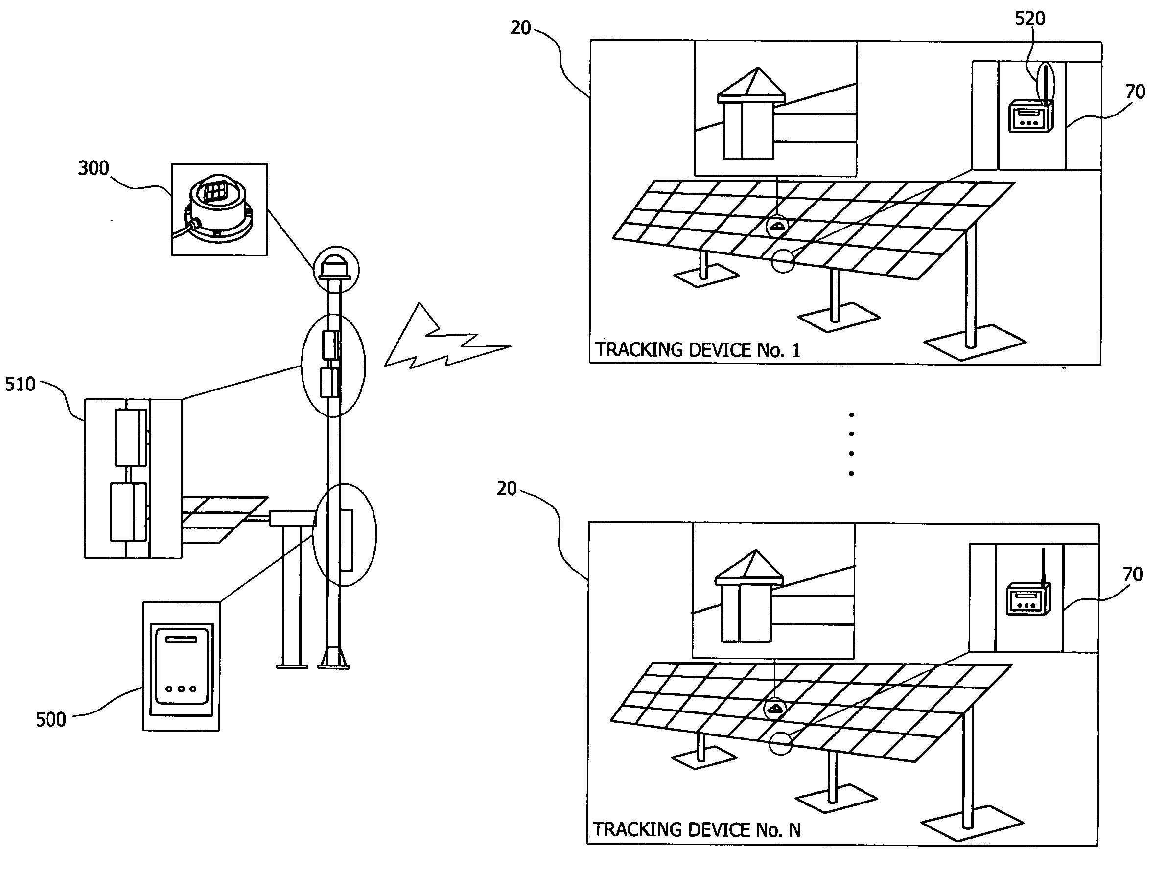
[0013]Therefore, the present invention has been made in view of the above problems, and the present invention provides a solar servo control tracking device performing remote servo-control and remote monitoring of a plurality of solar module assemblies through remote communication by a control signal in accordance with a solar azimuth measured by a single solar cell sensor, and smoothly driving six or more solar module assemblies in which a plurality of solar panels is arranged in the form of a matrix to produce a maximal electric power with a single power transmission, so that expense can be cut down and efficiency of generating electricity from the solar energy can be maximized.
[0028]According to the present invention, since accuracy, rapid response, and tracking accuracy with respect to the operating angle control performed for the solar module assemblies are improved, efficiency of photovoltaic power generation can be optimized, and a plurality of solar module assemblies can be controlled in an optimized state, at once, by a single solar cell sensor unit. The high torque driving unit can generate a high torque to drive the solar module assemblies with 20% higher weight than the existing solar module assemblies so that efficiency of the photovoltaic power generation can be maximized.

Problems solved by technology

Since the existing CdS type light sensor is fixed to top of the solar module assembly to detect a solar azimuth entered in a specific azimuth, it is difficult to detect the solar azimuth when weather is changeable, that is, alternating cloudy and clear.
The existing CdS type light sensors are attached to the top of every solar module assembly one by one so that cost increases, and due to characteristics of the CdS, the solar azimuth detected by the tracking device in a power station has a large error range.
A drive unit using an existing DC motor has insufficient driving torque to drive more than six solar module assemblies.
Since a DC motor is employed as a driving source of the solar module assembly and a switching mode power supply converting commercial AC 220V into DC power is required, that becomes an economic burden.
Since a driven angle of the solar module assembly is estimated by counting pulses generated per one revolution using a proximity sensor in order to detect the driven angle of the solar module assembly, it is difficult to precisely control the driven angle of the solar module assembly.
Therefore, it is expensive to maintain the solar module assembly.

Method used


Image

  • Solar servo control tracking device
  • Solar servo control tracking device
  • Solar servo control tracking device

Examples


Embodiment Construction

[0048]Hereinafter, preferred embodiments of the present invention will be described in detail with reference to the accompanying drawings.

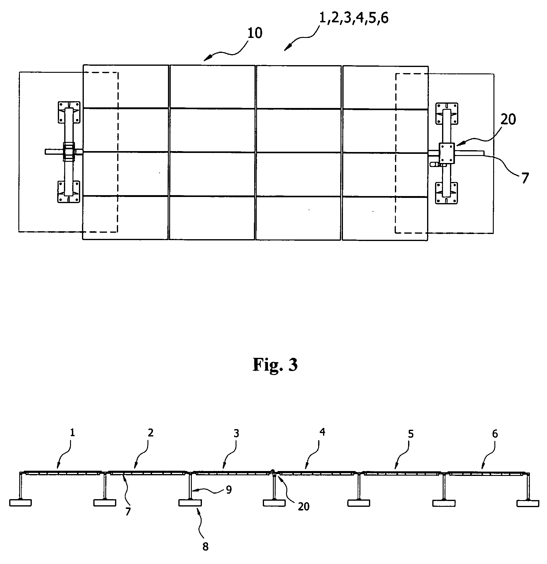
[0049]FIGS. 1 to 11 illustrate a technical configuration of an integrated control device and a solar servo-control tracking device according to an embodiment of the present invention, in which: FIG. 1 is a view illustrating technical configuration of a solar servo-control tracking device according to an embodiment of the present invention; FIG. 2 is a plan view illustrating an assembly of a single solar module assembly of the solar servo-control tracking device according to the embodiment of the present invention; FIG. 3 is a front view illustrating a solar tracking device according to the embodiment of the present invention; and FIG. 4 is a side view of the solar tracking device in FIG. 3 and illustrating an operating range of a driving angle.

[0050]FIG. 5 is a detailed front view illustrating the structure of a power transmission of the solar tra...


PUM


Abstract

A solar servo control tracking device is disclosed. The device includes: an integrated control device having a solar cell sensor unit detecting luminance at a solar azimuth, and an integrated control panel transmitting a control signal at a maximal solar azimuth, calculated by comparing a solar azimuth from the luminance at a solar azimuth; and solar tracking devices, respectively having a tracking device controller receiving the control signal via a wireless link, a high torque driving unit with an AC single phase inductor to generate driving torque by the control signal from the tracking device controller, solar module assemblies driven by the high torque driving unit to track the solar azimuth in accordance with the control signal, and an operating angle sensor unit installed to the high torque driving unit to detect operating angles of the solar module assemblies that track the sun by the control signal.

Description

BACKGROUND OF THE INVENTION[0001]1. Field of the Invention[0002]The present invention relates to a solar servo control tracking device, and more particularly, to a solar servo control tracking device remotely servo-controlling and remotely monitoring a solar module assembly and being smoothly driven in accordance with a solar azimuth.[0003]2. Description of the Related Art[0004]An existing solar tracking device uses a power transmission including a direct current (DC) motor and a worm gear to provide a driving force to a photo-conductive cell (CdS) and a solar module assembly by measuring luminance and a proximity sensor to detect a rotation angle of the tracking device.[0005]However, the related art has the following disadvantages:[0006]Since the existing CdS type light sensor is fixed to top of the solar module assembly to detect a solar azimuth entered in a specific azimuth, it is difficult to detect the solar azimuth when weather is changeable, that is, alternating cloudy and cl...

Claims


Application Information

Patent Timeline
IPC IPC(8): F24J2/38F24S50/20
CPCF24J2/38F24J2/541F24J2002/5465H02S20/00Y02E10/47Y02E10/50G01S3/7861H02S20/32H02S40/32H02S20/10H02S40/42F24S50/20F24S2030/135F24S30/425H02S40/30
Inventor CHOI, KEE HYOKLIN, IN CHEOLKIM, HYUN WOOWOO, HYEOK JAESHIN, KYOO JAE
Owner SDN
Learn More