High-power fiber amplifier

a fiber amplifier and high-power technology, applied in the field of optical devices, can solve the problems of reducing the optical energy of the signal being amplified, creating unacceptable noise, and unavoidable online effects

Inactive Publication Date: 2009-09-17
CORP DE LECOLE POLYTECHNIQUE DE MONTREAL
View PDF0 Cites 23 Cited by
  • Summary
  • Abstract
  • Description
  • Claims
  • Application Information

AI Technical Summary

Problems solved by technology

For the highest powers, one requires a rather large core area (large mode area fibers), because the optical intensities otherwise become too high and nonlinear effects become unavoidable.
When the optical intensity in the fiber rises above a corresponding threshold, a stimulated regime is reached where the Stokes wave is amplified, significantly depleting the optical energy from the signal being amplified and creating unacceptable noise.
The propagation of the signal in a high order mode however complicates its coupling at the output of the amplifier, necessitating the use of external components such as a phase plate as shown in FIGS. 1A and 1B of Ramachandran.
The proper control of the optical fiber fabrication process to obtain such complex profile is however very difficult to achieve, as commented on by SAHU et al.

Method used


Image

  • High-power fiber amplifier
  • High-power fiber amplifier
  • High-power fiber amplifier

Examples


Embodiment Construction

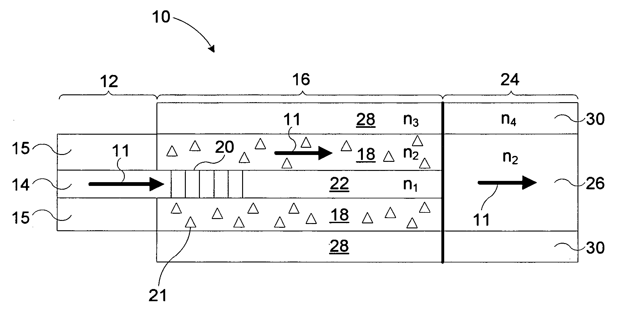
[0024]Embodiments of the present invention provide high-power amplifiers which avoid or minimize the onset of non-linear effects while still allowing for a relative ease of construction and design.

[0025]Light amplifiers according to such embodiments may be used to increase the power of any appropriate light signal, depending of the intended application of the device. The terms “light” or “optical” are used herein to refer to any appropriate portion of the electromagnetic spectrum. The light signal to be amplified may have various spectral, temporal or intensity characteristics, as dictated by its intended use. As mentioned above, the wavelength range 1.5-1.6 μm is for example of particular interest for applications such as laser cutting and machining, and in view of the compatibility of wavelengths within that range with existing telecommunications components. It will however be understood that the amplifiers of the present invention are not limited to such a context and may be adap...


PUM


Abstract

Fiber light amplifiers adapted for high power application are provided. In embodiments of the invention, the light signal to be amplified is coupled to a cladding mode of an active waveguide region which is cladding doped. The amplified light is coupled to an output fiber have waveguiding properties matching those of the active cladding of the active waveguide region. In other embodiments, two or more amplifying stages are provided coupled by a wavelength selective loss element which couples the Stokes wave co-propagating with the signal to be amplified out of the signal guiding mode prior to the onset of SRS.

Description

FIELD OF THE INVENTION[0001]The present invention relates to the field of optical devices and more particularly concerns high power fiber amplifiers.BACKGROUND OF THE INVENTION[0002]High-power amplifiers, for example in the relatively eye-safe wavelength range 1.5-1.6 μm, are of great interest for scientific and engineering applications, such as laser cutting and machining. Their compatibility with telecommunications components provides the possibility to use lower-cost and widely available devices. An Er3+ doped fiber is the best choice in this wavelength range. The high Er3+ concentration which is required for efficient operation of an erbium-doped fiber amplifier (EDFA) and permits the use of shorter fibers to increase threshold powers for unwanted nonlinear effects such as stimulated Raman scattering (SRS) and stimulated Brillouin scattering (SBS), results in an increase in a refractive index relative to pure silica. Fiber amplifiers doped with other rare-earth elements are also...

Claims


Application Information

Patent Timeline
Patent Type & Authority Applications(United States)
IPC IPC(8): H01S3/00
CPCG01M11/319G02B6/02095H01S3/0675H01S3/06754H01S2301/03H01S3/094007H01S3/10023H01S3/302H01S2301/02H01S3/06758
Inventor KASHYAP, RAMANNEMOVA, GALINA
Owner CORP DE LECOLE POLYTECHNIQUE DE MONTREAL
Why Eureka
Try Eureka