Communication system, receiver and reception method

Inactive Publication Date: 2009-09-17
SONY CORP
View PDF12 Cites 32 Cited by
  • Summary
  • Abstract
  • Description
  • Claims
  • Application Information

AI Technical Summary

Benefits of technology

[0030]The present invention compensates for the delay caused by an amplifier adapted to expand the amplitude.
[0031]This p

Problems solved by technology

However, although the techniques disclosed in Non-Patent Document 1 and Patent Document 1 were able to solve the first problem described above, it was impossible for these techniques to provide a sufficiently improved transmission rate due to the frequency characteristics of, and the delay caused by, the amplifiers 31 and 32 adapted to expand the amplitude.
More specifically, the data ou

Method used


Image

  • Communication system, receiver and reception method
  • Communication system, receiver and reception method
  • Communication system, receiver and reception method

Examples


Embodiment Construction

[0045]The preferred embodiments of the present invention will be described below with reference to the accompanying drawings.

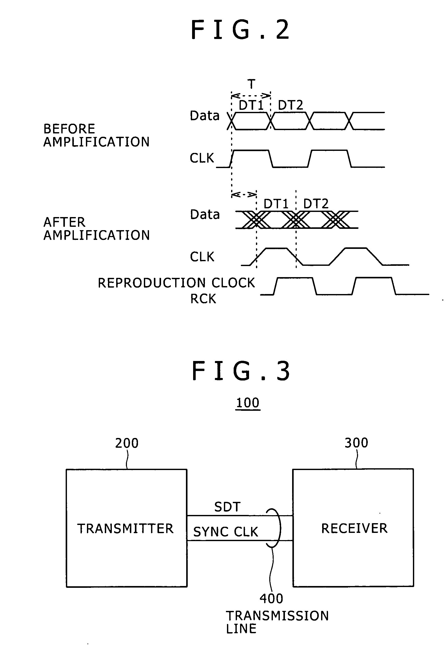
[0046]FIG. 3 is a diagram illustrating the basic configuration of a communication system according to an embodiment of the present invention. FIG. 4 is a diagram more specifically illustrating a transmitter and receiver shown in FIG. 3.

[0047]A communication system 100 includes a transmitter 200, receiver 300 and transmission line 400.

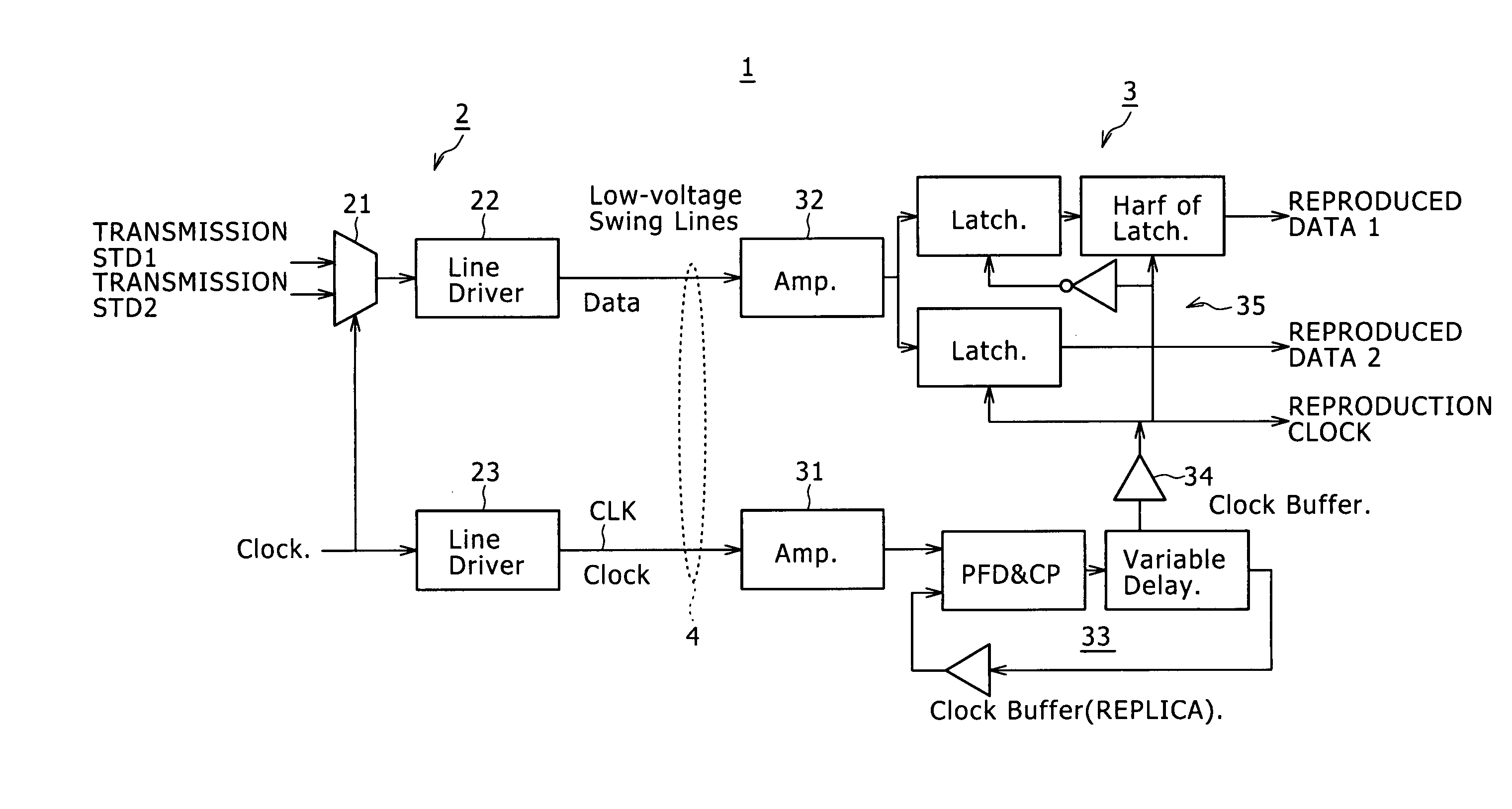
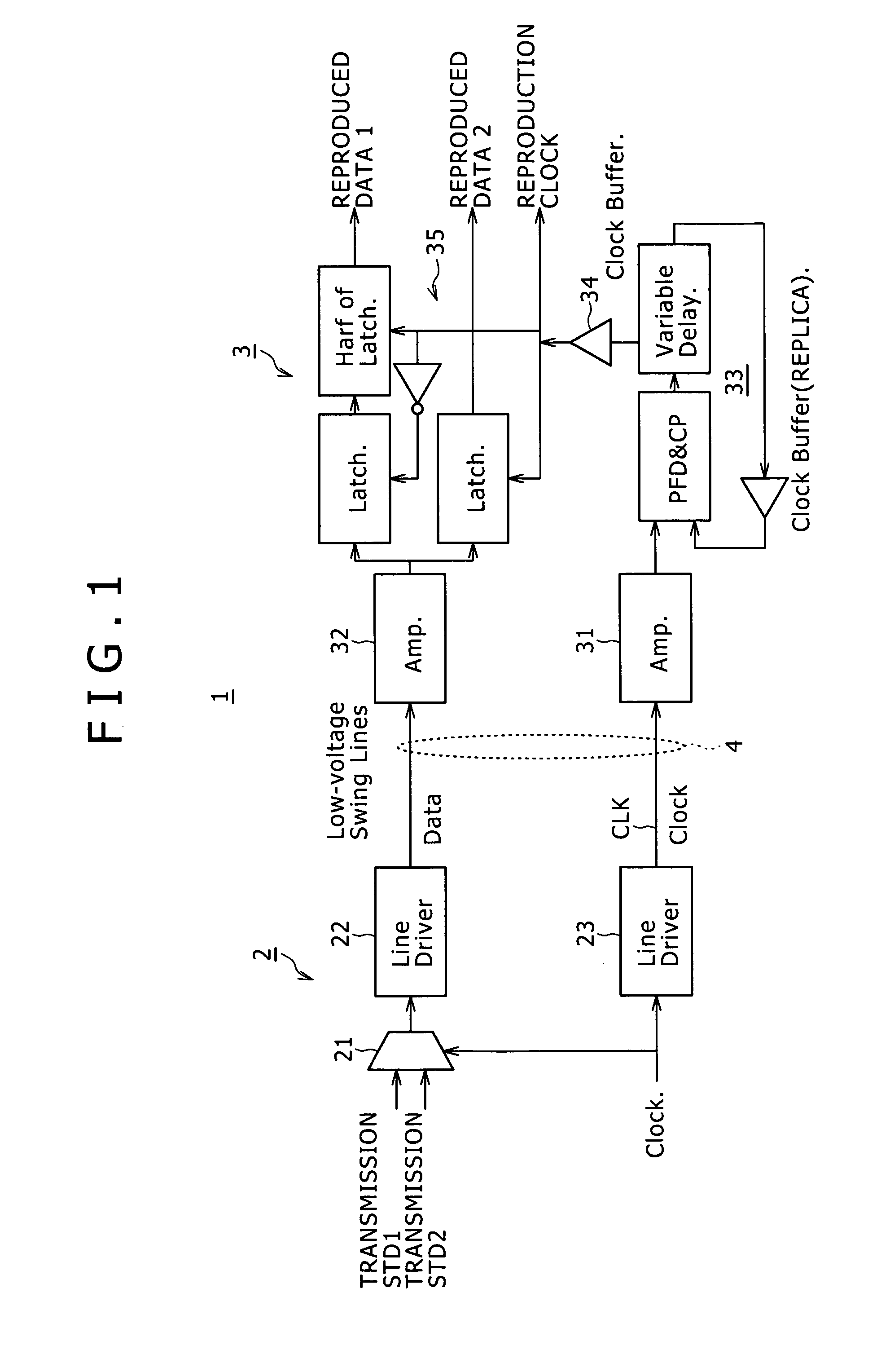
[0048]The transmitter 200 includes a serializer 210, clock generator 220 and line driver 230. The serializer 210 converts N-bit parallel data, which is updated every time T, into 1-bit serial data which is updated every time T / N. The clock generator 220 generates a synchronizing clock SYNC CLK whose level changes at the end of the serialization. The line driver 230 transmits serial data at a low amplitude close to the ground potential (e.g., 200 mV (0.2 V) or 300 mV (0.3 V)). The synchronizing clock SYNC CLK and serial data SDT ar...


PUM


Abstract

A communication system includes: a transmitter adapted to transmit a synchronizing clock and serial data synchronous with the synchronizing clock over a line at low amplitude; and a receiver adapted to receive the serial data and synchronizing clock from the transmitter. The receiver includes an amplifier adapted to amplify the received synchronizing clock of low amplitude to restore the clock to its original amplitude, a latched comparator adapted to latch the received serial data in synchronism with a reproduction clock, and a phase-locked circuit.

Description

BACKGROUND OF THE INVENTION[0001]1. Field of the Invention[0002]The present invention relates, for example, to a communication system, receiver and reception method using a low-amplitude data transmission technique capable of providing high-speed data transmission between chips in proximity to each other.[0003]2. Description of the Related Art[0004]In related art, the I / O (input / output) standards commercialized to date for high-speed data transmission between chips in proximity to each other such as SSTL—1.8 and LVDS have the following drawbacks.[0005]Firstly, if the supply voltage was changed or a finer manufacturing process was introduced, it was impossible to establish connection. Therefore, it was necessary to take the trouble of adding a manufacturing step adapted to manufacture an I / O circuit with elements having an obsolete structure, which resulted in reduced performance and increased cost.[0006]Secondly, although the power consumption of the line drivers alone is as much as...

Claims


Application Information

Patent Timeline
IPC IPC(8): H04L27/00H03D3/24
CPCH04L7/0008H03L7/18
Inventor YAMADA, TAKAAKIKIHARA, HIROKISUGIOKA, TATSUYAOWA, HISASHINIKI, TAICHISHIMOMURA, YUKIO
Owner SONY CORP
Why Eureka
Try Eureka