Optical fiber and optical fiber ribbon

Active Publication Date: 2009-09-17
FURUKAWA ELECTRIC CO LTD
View PDF6 Cites 21 Cited by
  • Summary
  • Abstract
  • Description
  • Claims
  • Application Information

AI Technical Summary

Benefits of technology

[0018]That is, according to the optical fiber of the first and second aspects of the present invention, it is possible to restrain delamination in the interface between the optical fiber and the coating resin such as the glass/primary layer interface which causes an increase in transmission loss by setting the extraction rate of the coating resin of the optical fiber when immersed in water at 60° C. for 168 hours to 1.5% or below. 168 hours is adopted because extractable from the coating resin saturates after a lapse of approximately 168 hours.
[0019]According to the optical fiber of the third aspect of the present invention, even when the ex

Problems solved by technology

In an optical fiber, transmission loss increases due to various external stress and microbends thereby caused.
When an optical fiber is used immersed in water for a long period of time, transmission loss may increase.
For example, Japanese Patent No. 2925099 (Patent Document 1) discloses that when an optical fiber ribbon is used in a high humidity atmosphere, extraordinary swelling occurs between a secondary layer and a colored layer or between a colored layer and a ribbon layer due to moisture absorption and this causes stress to apply to quartz glass and thereby causes transm

Method used


Image

  • Optical fiber and optical fiber ribbon
  • Optical fiber and optical fiber ribbon

Examples


Example

[0025]With reference now to drawings, embodiments of the present invention will be explained below.

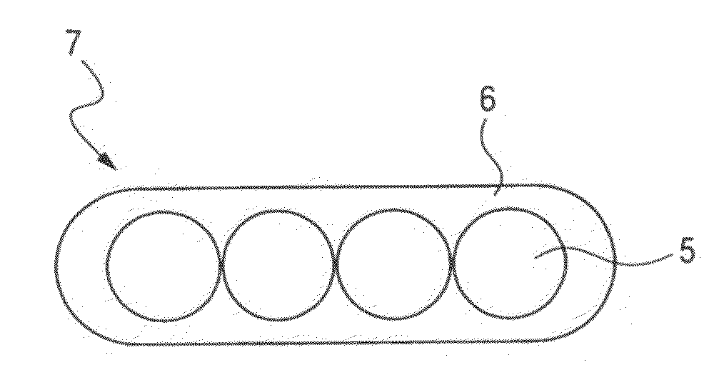
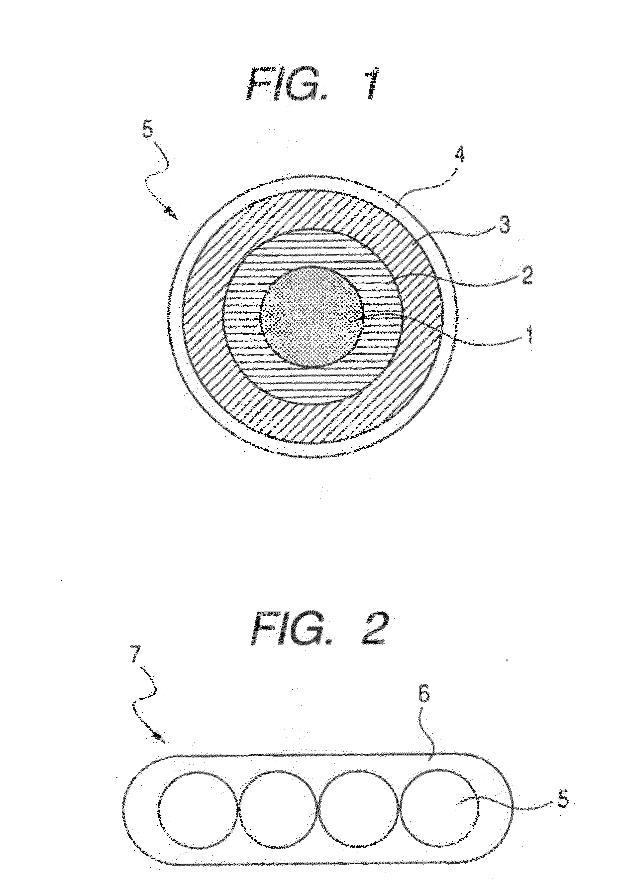
[0026]The following mode is preferable as the best mode for carrying out the present invention. That is, an optical fiber is coated with three layers of coating resin of a primary layer, secondary layer and colored layer, to fabricate an optical fiber. Ultraviolet cured resin is used for each resin. Moreover, a plurality of these optical fibers are arranged in parallel in a plane, and coated with ribbon resin made of ultraviolet cured resin all together to form an optical fiber ribbon.

[0027]As an embodiment of the present invention, several types of optical fibers 5 were fabricated by coating an optical fiber 1 made of quartz glass shown in FIG. 1 with three layers of coating resin of a primary layer 2, a secondary layer 3 and a colored layer 4. Ultraviolet cured resin is used for each resin. The ultraviolet cured resin comprises oligomer, dilute monomer, photoinitiator, chain transfer...


PUM


Abstract

The present invention relates to an optical fiber accommodated in an optical fiber cable, and more particularly, to an optical fiber which optimizes optical fiber coating resin and color resin and restrains an increase in transmission loss of the optical fiber due to an operating environment and aged deterioration and provides an optical fiber and optical fiber ribbon without any increase of transmission loss irrespective of the operating environment and aged deterioration, and especially when exposed to water or high humidity.
The optical fiber is an optical fiber coated with at least two layers of coating resin, wherein the outermost coated coating resin is a colored layer made of color resin and when the optical fiber is immersed in water which is heated to 60° C. for 168 hours, an extraction rate of the coating resin of the optical fiber is set to 1.5 mass percent or below.

Description

TECHNICAL FIELD[0001]The present invention relates to an optical fiber or ribbon accommodated in an optical fiber cable. More specifically, the present invention relates to an optical fiber in which coating resin and color resin for the optical fiber are optimized and increases of transmission loss of the optical fiber due to an operating environment and aged deterioration are suppressed.BACKGROUND ART[0002]In a drawing process of quartz glass, the outer surface of an optical fiber is immediately coated with coating resin to prevent the degradation in strength of the optical fiber. As the optical fiber coating resin, ultraviolet cured resin is mainly used. As the ultraviolet cured resin, a urethane acrylate based resin or epoxy acrylate based resin is used.[0003]In an optical fiber, transmission loss increases due to various external stress and microbends thereby caused. Therefore, to protect the optical fiber from such external stress, an optical fiber is generally provided with a ...

Claims


Application Information

Patent Timeline
IPC IPC(8): G02B6/44G02B6/036
CPCG02B6/4403G02B6/02395G02B6/4482
Inventor NAKAJIMA, YASUOTANAKA, HIROKIARASHITANI, YOSHIHIROMOCHIZUKI, KOUJIOKADA, MITSUNORI
Owner FURUKAWA ELECTRIC CO LTD
Why Eureka
Try Eureka