Ultralight soundproof material

Inactive Publication Date: 2006-09-14
TAKEHIRO CO LTD +1
View PDF6 Cites 35 Cited by
  • Summary
  • Abstract
  • Description
  • Claims
  • Application Information

AI Technical Summary

Benefits of technology

[0021] The object of the invention is thus to enhance sound insulation from direct noise incoming from a vehicle panel and more specifically to raise transmission loss in a medium to high frequency domain generally having less transmission loss. The object of the invention is also to ensure sufficient sound absorption even in a thin-wall sound absorption layer of an actual odd-shaped product an

Problems solved by technology

The high area-weight of rubber sheet, however, causes a significant transmission resonance in a low frequency domain to drastically lower the transmission loss.
The structure of FIG. 28 has also a double-wall structure of the air-permeable surface layer and the panel, however, the surface layer lets air through, and this causes sound leakage in a high frequency domain.
The structure of FIG. 28 accordingly does not give sufficient transmission loss for sound insulation.
The automobile of some vehicle structure has large effects of direct noise.
The structure of FIG. 28 may give an insufficient transmission loss (see FIG. 29(a)) and thus fail to attain the required stillness in the vehicle interior.
Reduction in thickness of the sound absorption layer thus results in the lowered sound absorbing power.
The thin wall portion has the lowered air-flow resistance than the other wall portion and does not give the sufficient so

Method used


Image

  • Ultralight soundproof material
  • Ultralight soundproof material
  • Ultralight soundproof material

Examples


first embodiment

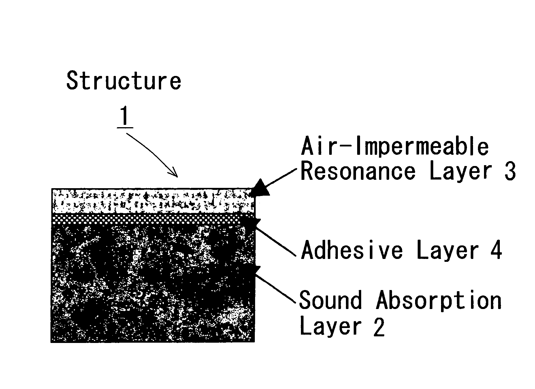
[0095] As shown in FIG. 3, a dash silencer 1 of a first embodiment has a two-layer structure of a sound absorption layer 2 and an air-impermeable resonance layer 3. The sound absorption layer 2 has an air permeability in a range of 10 to 50 cm3 / cm2·sec in the case of thermoplastic felt or an air permeability of not greater than 10 cm3 / cm2·sec in the case of polyurethane foam. An adhesive layer 4 is interposed between the sound absorption layer 2 and the air-impermeable resonance layer 3 for bonding the two layers 2 and 3 to each other. The dash silencer 1 takes advantage of resonance at the interface between the sound absorption layer 2 and the air-impermeable resonance layer 3 for sound absorption.

[0096] As shown in FIG. 4, an iron dash panel 10 parts a vehicle interior from a vehicle exterior (an engine room), and the dash silencer 1 of the first embodiment is formed along the inner surface of the vehicle interior. The dash silencer 1 is designed to be ultra light in weight for t...

second embodiment

[0116]FIG. 10(a) shows a dash silencer 201 of a second embodiment. The dash silencer 201 of the second embodiment has a similar structure to that of the dash silencer 1 of the first embodiment, so the explanation about the first embodiment can be applied hereto. The primary difference is that a sound absorption layer 202 of the dash silencer 201 has a high-density sound absorption layer 202a and a low-density sound absorption layer 202b having different densities. The high-density and low-density sound absorption layers 202a and 202b are arranged on the side of the dash panel 10, whereas an air-impermeable resonance layer 203 is arranged on the side of the vehicle interior. The low-density sound absorption layer 202b is bonded to the dash panel 10.

[0117] One face of the high-density sound absorption layer 202a is bonded to the air-impermeable resonance layer 203 via an adhesive layer 204. The high-density sound absorption layer 202a has a density in a range of 0.05 to 0.20 g / cm3 an...

example 2

[0124] The structure of Example 2 was similar to the structure of Example 1, except the varying-density of the sound absorption layer. The high-density sound absorption layer 202a was made of thermoplastic felt (of reused synthetic fibers and PE fibers with PET used as binding fibers) and had a density of 0.100 g / cm3, a thickness of 10 mm, an area-weight of 1000 g / cm2, and an initial compression repulsive force of 200 N. The low density sound absorption layer 202b was made of cotton fiber felt and had a density of 0.04 g / cm3, a thickness of 10 mm, an area-weight of 400 g / m2, and an initial compression repulsive force of 50 N. The adhesive force of the adhesive layer 204 was 5 N / 25 mm. The high-density sound absorption layer 202a and the low-density sound absorption layer 202b may be made of PET felt and joined together by needle punching.


PUM


Abstract

A sound insulator of the invention includes a sound absorption layer 202 and an air-impermeable resonance layer 203, which are bonded to each other via an adhesive layer 204. The sound absorption layer 202 has a thickness in a range of 5 to 50 mm and an area-weight of not greater than 2000 g/m2. The sound absorption layer 202 has a two-layer structure of a high-density sound absorption layer 202a and a low-density sound absorption layer 202b, which have different densities. The high-density sound absorption layer 202a is bonded to the air-impermeable resonance layer 203 via the adhesive layer 204 and has a density in a range of 0.05 to 0.20 g/cm3 and a thickness in a range of 2 to 30 mm. The low-density sound absorption layer 202b is bonded to the other face of the high-density sound absorption layer 202a, which is opposite to the air-impermeable resonance layer 203, via an adhesive layer 202c and has a density in a range of 0.01 to 0.10 g/cm3 and a thickness in a range of 2 to 30 mm. The structure of this sound insulator effectively reduces a noise level in a voice-tone frequency band, especially in a high frequency domain, thereby efficiently enhancing the clarity of conversion in a vehicle interior.

Description

BACKGROUND OF THE INVENTION [0001] 1. Field of the Invention [0002] The present invention relates to an ultra-light sound insulator that prevents propagation of noise and other undesired sound from an engine room or any other vehicle exterior into a vehicle interior. More specifically the invention pertains to an ultra-light sound insulator that is extremely light in weight and effectively absorbs noise and other undesired sound to prevent their propagation into the vehicle interior. [0003] 2. Description of the Related Art [0004] Patent Document 1 discloses a multifunctional kit (41), which is used in vehicles to attain noise reduction and heat insulation and more specifically to have sound-absorbing, sound-insulating, oscillation-damping, and heat-insulating effects on floor insulation, end wall insulation, door covering, and roof inner covering. The multifunctional kit (41) includes at least one areal vehicle part (11) and a multi-layer noise-reducing assembly package (42). The a...

Claims


Application Information

Patent Timeline
IPC IPC(8): F02B77/13B60R13/08G10K11/168
CPCB60R13/0815G10K11/16G10K11/168Y10T428/249953Y10T428/249987Y10T428/249982
Inventor INOUE, TORUISHIKAWA, MASAKIISHIKAWA, YOUHEIMATSUYAMA, SOHEIMORI, HIDEYUKI
Owner TAKEHIRO CO LTD
Why Eureka
Try Eureka