Liquid injection device of fuel cell, fuel cell and fuel cartridge
- Summary
- Abstract
- Description
- Claims
- Application Information
AI Technical Summary
Benefits of technology
Problems solved by technology
Method used
Image
Examples
first embodiment
[0101]Referring now to FIGS. 7A to 10B, a bayonet coupler structure (key-key way coupling joint) consists of a cartridge and a cell main body of a first embodiment will be described below.
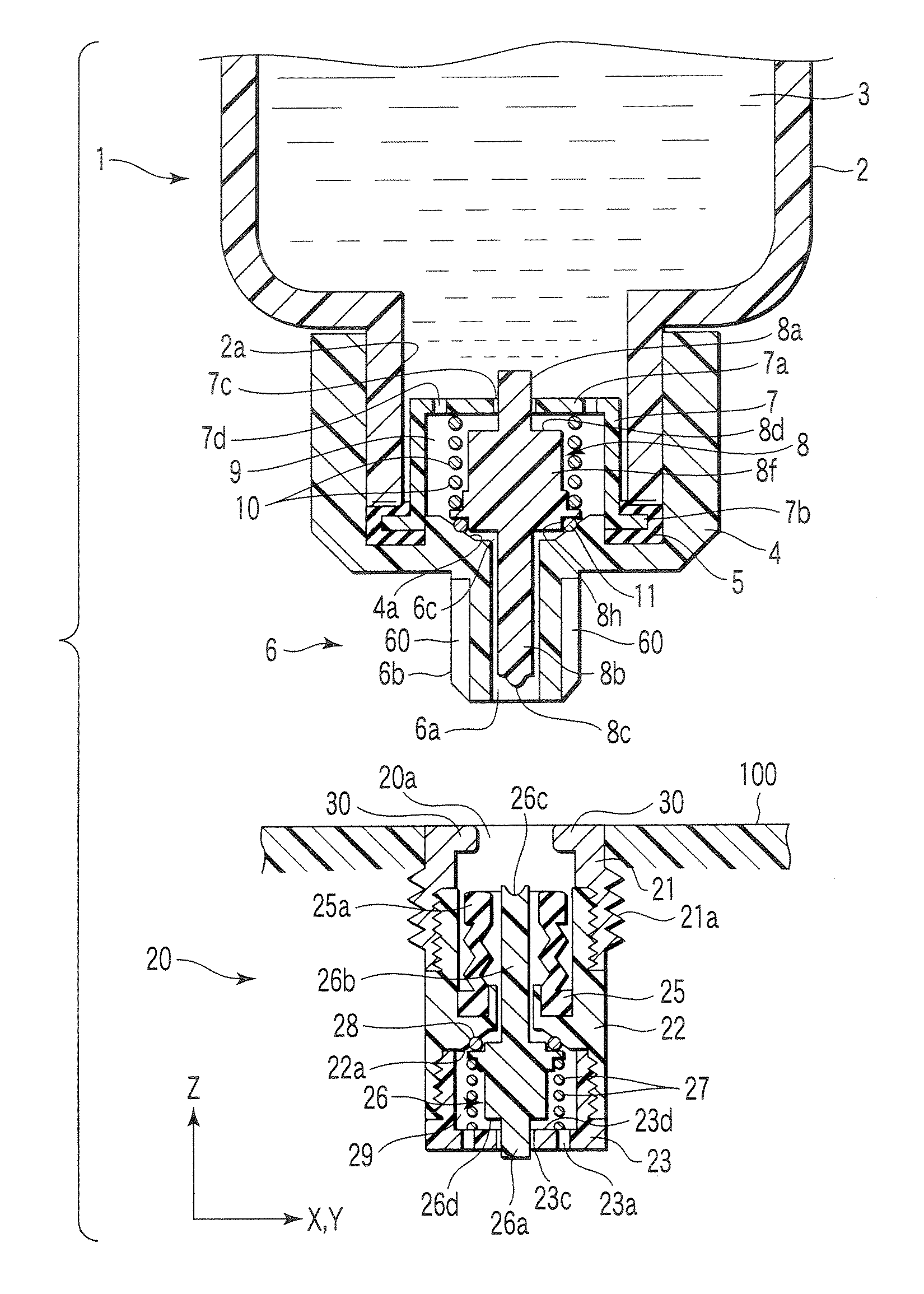
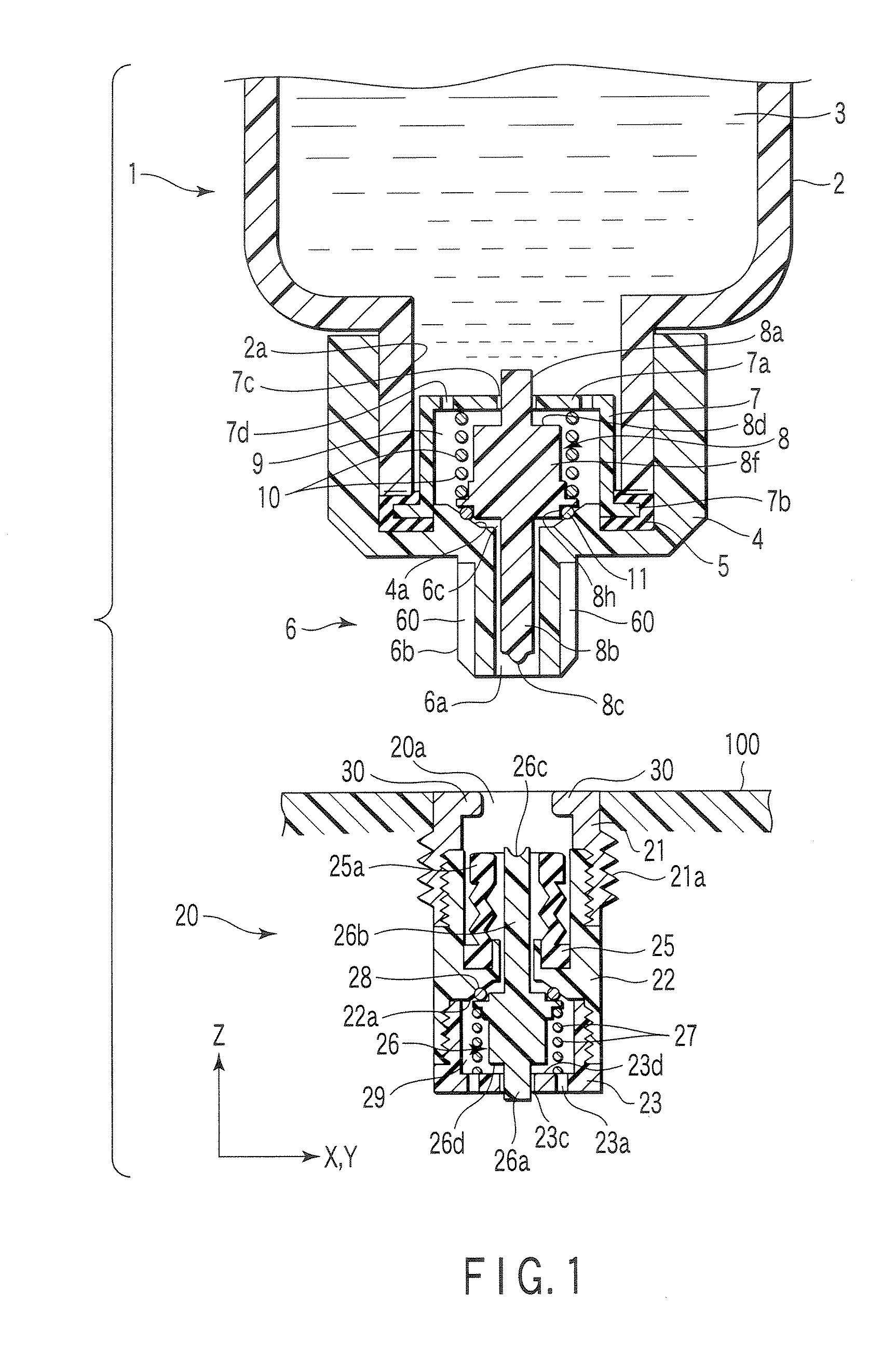
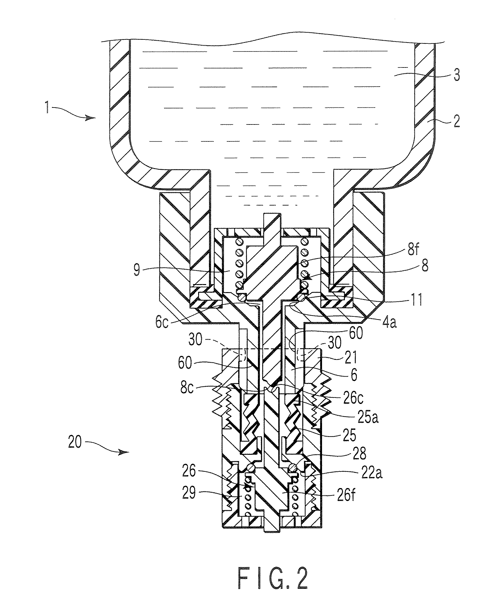
[0102]In the first embodiment, a groove 6g is provided in the outer circumference of a male type cartridge nozzle 6, and the protrusion 30 is provided in the inner circumference of a female type injection port 20 of the cell main body side. The cartridge nozzle 6 as a bayonet coupler element (key way coupling element) has two inverted L-figure grooves 60 provided in the outer circumference as shown in FIGS. 7A, 7B, and 8. The grooves 60 have protrusion insertion ports distributed by the 180-degree axial center as shown in FIG. 7A, and are formed in an inverted L figure (the shape on two-dimensional projection plane from the side) rotated and displaced by about 90 degrees clockwise in the circumferential direction when extended from the protrusion insertion ports in the axial direction as shown in F...
second embodiment
[0113]Referring now to FIGS. 11A, 11B, 12A, and 12B, the structures of a cartridge and a cell main body coupler of a second embodiment will be described below.
[0114]In the second embodiment, a protrusion 62 is provided in a cartridge nozzle 6A, and a groove 32 is provided in an injection port 20A of the cell main body side. The cartridge nozzle 6A as a bayonet coupler element (key coupling element) has two protrusions 62 provided in the outer circumference as shown in FIG. 11A. The protrusions 62 are distributed by the 180-degree axial center in a nozzle main body 61 as shown in FIG. 11A, and provided in the outer circumference near the leading end of the nozzle main body 61 as shown in FIG. 15B.
[0115]The injection port 20A of the cell main body side as a bayonet coupler element (key way coupling element) has two grooves 32 in the inner circumference as shown in FIG. 12A. The grooves 32 have protrusion insertion ports distributed by the 180-degree axial center as shown in FIG. 12A, ...
third embodiment
[0117]Referring now to FIGS. 13A, 13B, 14A, and 14B, the structures of a cartridge and a cell main body coupler of a third embodiment will be described below.
[0118]In the third embodiment, a protrusion 63 is provided in a cartridge nozzle 6B, and a groove 33 is provided in an injection port 20B of the cell main body side. The cartridge nozzle 6B as a bayonet coupler element (key coupling element) has three protrusions 63 provided in the outer circumference as shown in FIG. 13A. The protrusions 63 are distributed by the 120-degree axial center in the nozzle main body 61 as shown in FIG. 13A, and provided in the outer circumference near the leading end of the nozzle main body 61 as shown in FIG. 13B.
[0119]The injection port 20B of cell main body side as a bayonet coupler element (key way coupling element) has the three grooves 33 in the inner circumference as shown in FIG. 14A. The grooves 33 have protrusion insertion ports distributed by the 120-degree axial center as shown in FIG. 1...
PUM
 Abstract
Description
Claims
Application Information
 - R&D
- Intellectual Property
- Life Sciences
- Materials
- Tech Scout
- Unparalleled Data Quality
- Higher Quality Content
- 60% Fewer Hallucinations
Browse by: Latest US Patents, China's latest patents, Technical Efficacy Thesaurus, Application Domain, Technology Topic, Popular Technical Reports.
© 2025 PatSnap. All rights reserved.Legal|Privacy policy|Modern Slavery Act Transparency Statement|Sitemap|About US| Contact US: help@patsnap.com


