Satellite communications with cableless seismographs

a cableless, satellite technology, applied in the field of seismic exploration, can solve the problems of increasing the weight of the cable that connects each geophone (or geophone array) to a central recording unit, difficult to maneuver a conventional seismic line into position, and often compromised image of the subsurface, so as to increase the power requirements of that unit, add cost and weight

Active Publication Date: 2009-09-17
BRITISH PETROLEUM DE
View PDF31 Cites 25 Cited by
  • Summary
  • Abstract
  • Description
  • Claims
  • Application Information

AI Technical Summary

Benefits of technology

[0020]One advantage of the instant approach is that it is less susceptible to local terrain variations than would be the case with conventional RF-based systems. More particularly, rugged terrain can create radio shadow zones, e.g., areas where the radio signal from one or more seismographs cannot be detected at the base station. This might be due to terrain, foliage, federal or other restrictions on broadcast power, etc. Of course, equipping each field unit with a radio adds cost, weight and increases the power requirements for that unit.

Problems solved by technology

However, for all of the advances that have been made in recent years in the technology of seismic processing, the resulting image of the subsurface is often compromised by the ability to get geophones into position to receive the returning subsurface signals.
In more particular, in rugged terrain it may be difficult to maneuver a conventional seismic line into position so that receivers can be placed where they need to be in accordance with the survey plan.
Additionally, as the length of the seismic line increases (because of increased geophone spacing, increased number of channels, and / or longer offsets) the weight of the cable that connects each geophone (or geophone array) to a central recording unit becomes increasingly burdensome and more difficult to maneuver.
The net result of the above is poorer coverage (because of missing receivers) in rugged terrain and increased expense.
However, current solutions to this problem have not proven to be entirely satisfactory.
It should be noted that in most circumstances there is insufficient bandwidth to simultaneously stream the seismic data from all of the (potentially many thousands of) geophones at once.
Communication between the recording station and remote seismographs (e.g., “field units”, “channels”) is obviously more difficult with wireless systems than it is with conventional cabled systems.
However, there are problems with these sorts of approaches.
As an example, since a typical seismic survey may utilize several thousand geophones at any one time transferring the data from each geophone to the base station can prove to be problematic.
In the case of a WiFi approach, communications tend to break down when thousands of receivers try to transmit seismic data simultaneously to a base station.
In brief, neither of these methods has been particularly successful.
Another disadvantage of land cableless seismic systems is that the remote seismographs are easily stolen.
The loss of the instrument is serious enough, but the cost of the data stored within the memory is typically hundreds or thousands of times greater than the cost of the instrument.
Obviously, laying out (which may require some foliage reduction) and then collecting miles of heavy seismic cables has an increased potential to damage vegetation and other aspects of the wilderness environment as compared with cableless system, thus making them increasingly attractive.

Method used


Image

  • Satellite communications with cableless seismographs
  • Satellite communications with cableless seismographs
  • Satellite communications with cableless seismographs

Examples


Embodiment Construction

[0031]While this invention is susceptible of embodiment in many different forms, there is shown in the drawings, and will herein be described hereinafter in detail, some specific embodiments of the instant invention. It should be understood, however, that the present disclosure is to be considered an exemplification of the principles of the invention and is not intended to limit the invention to the specific embodiments or algorithms so described.

General Environment of the Invention

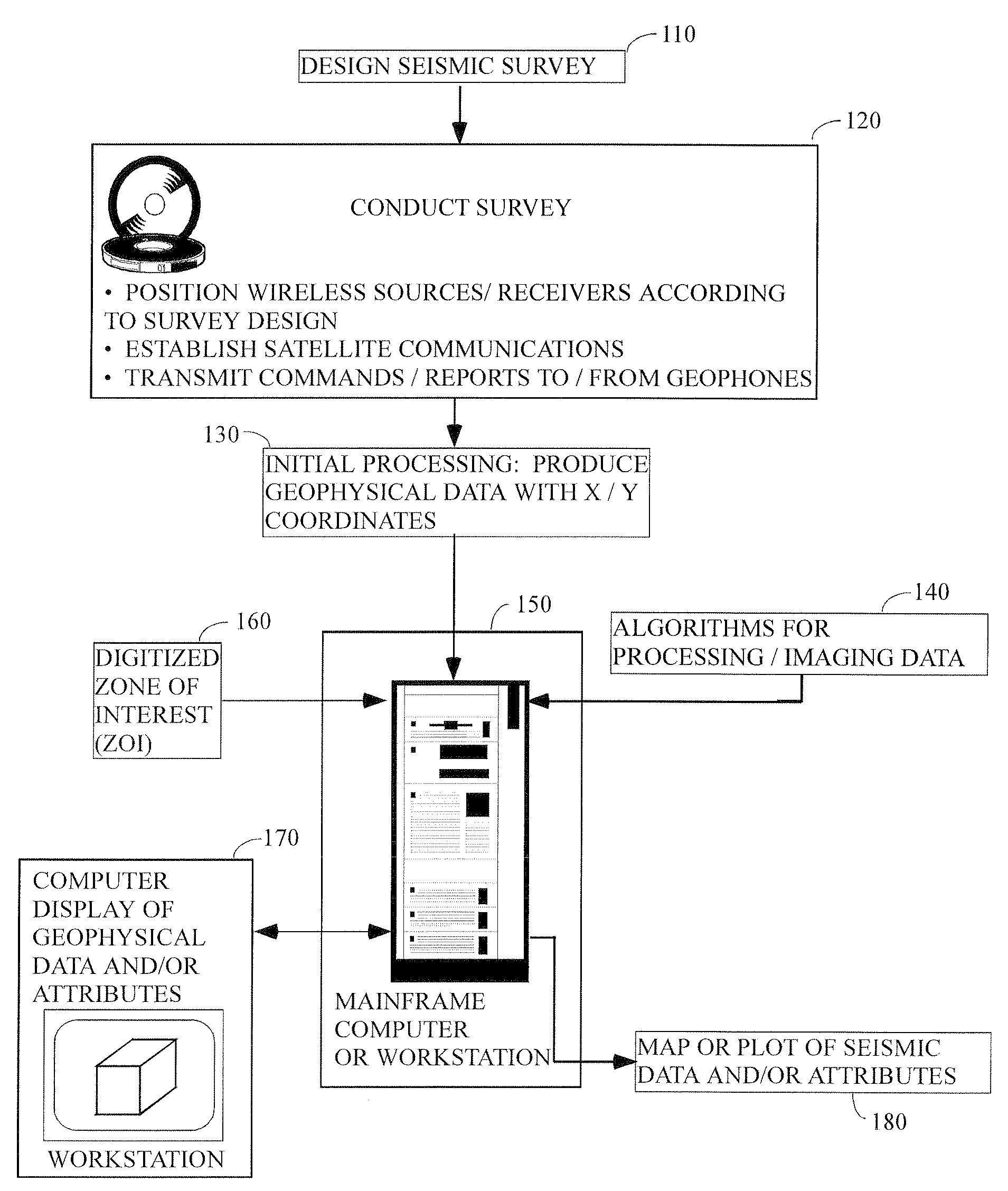
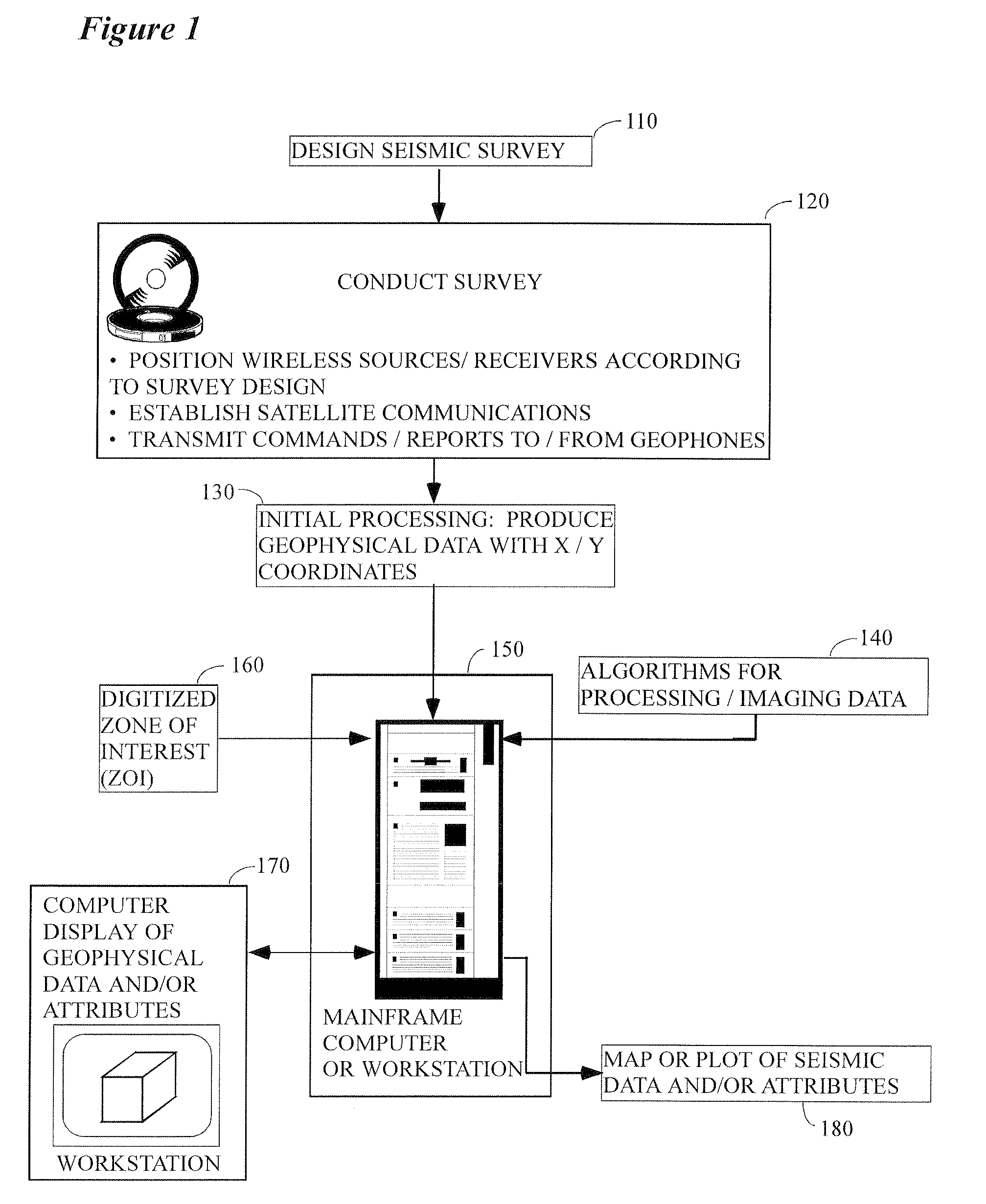
[0032]FIG. 1 illustrates the general environment in which the instant invention would typically be used. Seismic data 110 are collected in the field over a subsurface target of potential economic importance and are typically sent thereafter to a processing center or other ground station. Seismic surveys might be conducted on either land or water, but for purposes of the instant invention land acquisition only will be considered. It should be noted that the instant invention would typically be utilized du...


PUM


Abstract

According to a preferred aspect of the instant invention, there is provided a system and method for using satellite communications satellites to control and receive data from a land cableless seismic system. The satellite transmission could transmit control signals (e.g. turn on/off) and receive signals from the remote seismograph units (seismic data, quality control parameters, status, location, etc.) which would subsequently be retransmitted to a processing center or other surface facility.

Description

CROSS REFERENCE TO RELATED CASES[0001]This application claims the benefit of U.S. Provisional Patent Application Ser. No. 61 / 037,244, filed on Mar. 17, 2008, and incorporates said provisional application by reference into this disclosure as if fully set out at this point.TECHNICAL FIELD[0002]This invention relates to the general subject of seismic exploration and, in particular, to methods for collecting seismic data for use in quantifying and visualizing complex subsurface structures.BACKGROUND OF THE INVENTION[0003]A seismic survey represents an attempt to image or map the subsurface of the earth by sending sound energy down into the ground and recording the “echoes” that return from the rock layers below. The source of the down-going sound energy might come, for example, from explosions or seismic vibrators on land, or air guns in marine environments. During a seismic survey, the energy source is placed at various locations near the surface of the earth above a geologic structure...

Claims


Application Information

Patent Timeline
Patent Type & Authority Applications(United States)
IPC IPC(8): G01V1/28G06F15/00G06F15/16H04B7/185
CPCG01V1/22
Inventor ROSS, ALLAN A.PFISTER, MICHAEL
Owner BRITISH PETROLEUM DE
Why Eureka
Try Eureka