Projection exposure method and projection exposure system therefor

Active Publication Date: 2009-09-24
CARL ZEISS SMT GMBH
View PDF16 Cites 2 Cited by
  • Summary
  • Abstract
  • Description
  • Claims
  • Application Information

AI Technical Summary

Benefits of technology

[0024]In some embodiments, the condition Δλ≧0.15 nm is fulfilled for an absolute value Δλ=αMAX−λMIN of the wavelength variation range. This allows higher degrees of freedom with respect to compensation of pressure and temperature dependent performance variations. Also, larger differences of the absolute refractive index of utilized solid transparent optical material may be compensated for, for example differences of up to 5×10⁻⁵. This increased flexibility allows to decrease the expenditure on expensive measurements and allows higher flexibility with respect to utilizing different types of optical materials. For example, fused silica material and / or crystalline fluoride materials from different manufacturers which typically differ slightly with respect to their optical properties, can be tolerated within the optical system. Higher flexibility with respect to utilizing materials allows to further optimize other parameters, such as lifetime and costs.
[0027]In some embodiments a gas-filled space adjacent to the mask is encapsulated to form an encapsulated space transparent to radiation interacting with the mask. This encapsulated space may be evacuated to such an extent that the oxygen concentration is below a critical value (e.g. <10% or <1% oxygen). It is also possible to purge the gas-filled space by introducing into the gas-filled space a purging gas effective to decrease the concentration of the absorbent species, such as oxygen, below a critical concentration. Although the purging may be effected without encapsulating the critical gas-filled space, the purging gas is preferably guided into the encapsulated space to remove the absorbent species as desired. In this case, purging gas can be used economically.

Problems solved by technology

Each variation of refractive index differences leads to additional imaging aberrations.

Method used


Image

  • Projection exposure method and projection exposure system therefor
  • Projection exposure method and projection exposure system therefor
  • Projection exposure method and projection exposure system therefor

Examples


Embodiment Construction

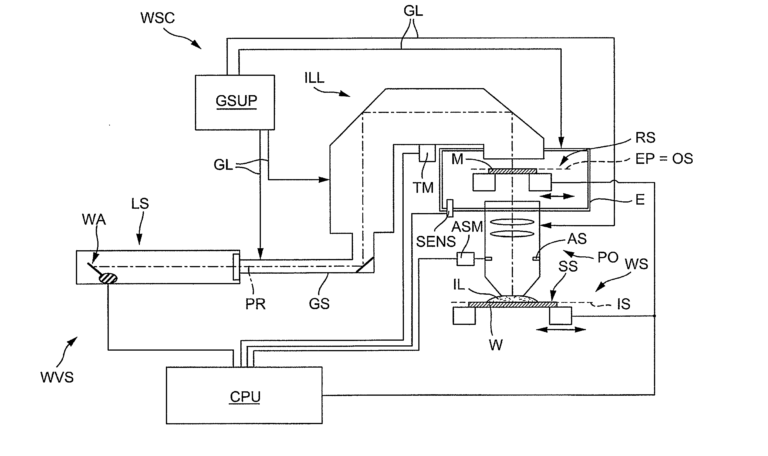
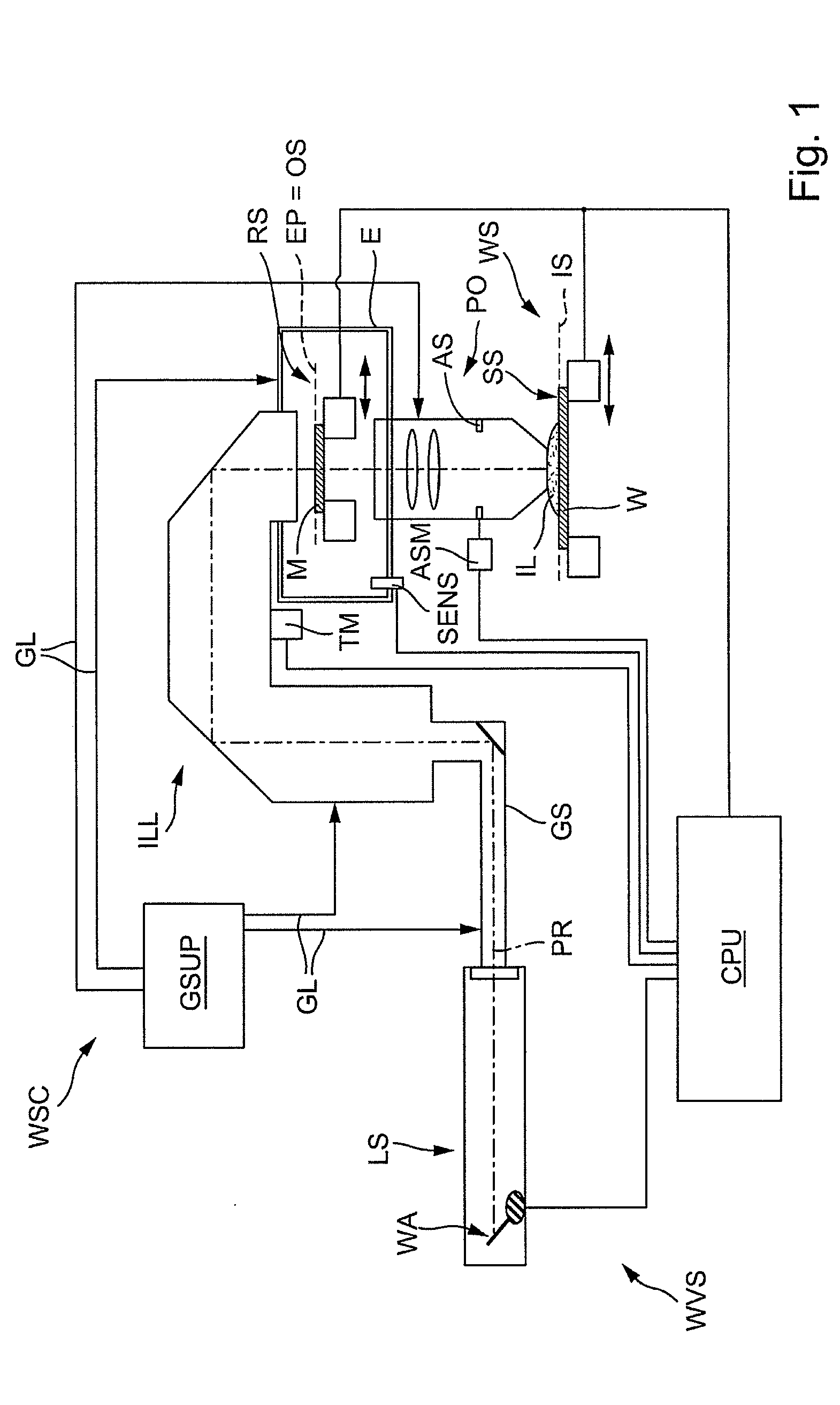
[0041]FIG. 1 shows a schematic drawing of an embodiment of a microlithographic projection exposure system configured as a wafer scanner WSC utilized for producing highly integrated semiconductor components by means of immersion lithography. The system includes a primary light source LS formed by a ArF excimer laser for generating primary radiation PR having a center wavelength λ˜=193.4 nm. The emitted beam of primary radiation PR is guided by a gas tight guiding system GS towards the entry of an illumination system ILL configured to transform the primary radiation into illumination radiation incident on a mask M bearing a pattern to be imaged onto light sensitive substrate W. The illumination system ILL includes a large number of optical components and optical units allowing to select various illumination modes such that the illumination mode can be switched, for example, between conventional illumination with a desired degree of coherence, annular field illumination and dipole or q...


PUM


Abstract

In a projection exposure method, primary radiation having a center wavelength λ is generated and guided through an illumination system along an illumination path and through a projection system along a projection path. The center wavelength is varied within a wavelength variation range Δλ having a lower limit λMIN≦λ and an upper limit λMAX≧λ. A specific absorption coefficient k(λ) of at least one gaseous absorbent species selected from the group consisting of oxygen (O2), ozone (O3) and water vapor (H2O) present in at least one gas-filled space along at least one of the illumination path and the projection path varies between a minimum absorption coefficient kMIN and a maximum absorption coefficient kMAX within the wavelength variation range such that an absorption ratio (kMAX / kMIN) exceeds 10. A concentration of the absorbent species within the gas-filled space is controlled such that an overall absorption variation effected by the absorbent species for all rays running along differing ray paths towards the image field is maintained below a predetermined absorption variation threshold value.

Description

CROSS-REFERENCE TO RELATED APPLICATIONS [0001]This application is a Continuation of International Application PCT / EP2007 / 008145, with an international filing date of Sep. 19, 2007, which was published under PCT Article 21(2) in English, and the complete disclosure of which is incorporated into this application by reference. This application claims the benefit under 35 U.S.C. 119(e)(1) of U.S. Provisional Application No. 60 / 847,097, filed Sep. 26, 2006. The disclosure of U.S. Provisional Application No. 60 / 877,743 is also hereby incorporated by reference into the present application. This application further claims priority under 35 U.S.C. 119(a) to European Patent Application No. 06 020 110.0 filed on Sep. 26, 2006. The entire contents of this application are also hereby incorporated by reference into the present application.BACKGROUND OF THE INVENTION[0002]1. Field of the Invention[0003]The invention relates to a projection exposure method for exposing a radiation-sensitive substra...

Claims


Application Information

Patent Timeline
IPC IPC(8): G03B27/54
CPCG03F7/70191G03F7/70941G03F7/70933G03F7/70575
Inventor KALLER, JULIANGRUNER, TORALF
Owner CARL ZEISS SMT GMBH
Why Eureka
Try Eureka