
Process Intensification In Microreactors

a microreactor and process intensification technology, applied in the field of chemical reaction devices, systems and methods, can solve the problems of limiting the potential for heat integration and process intensification, limiting the thermal efficiency of the necessary heat exchange, and the cost of system scale-up is typically linear, so as to achieve the effect of increasing the purity of carbon dioxide effluen

Inactive Publication Date: 2009-09-24
UNIV OF CONNECTICUT
View PDF21 Cites 20 Cited by
  • Summary
  • Abstract
  • Description
  • Claims
  • Application Information

AI Technical Summary

Benefits of technology

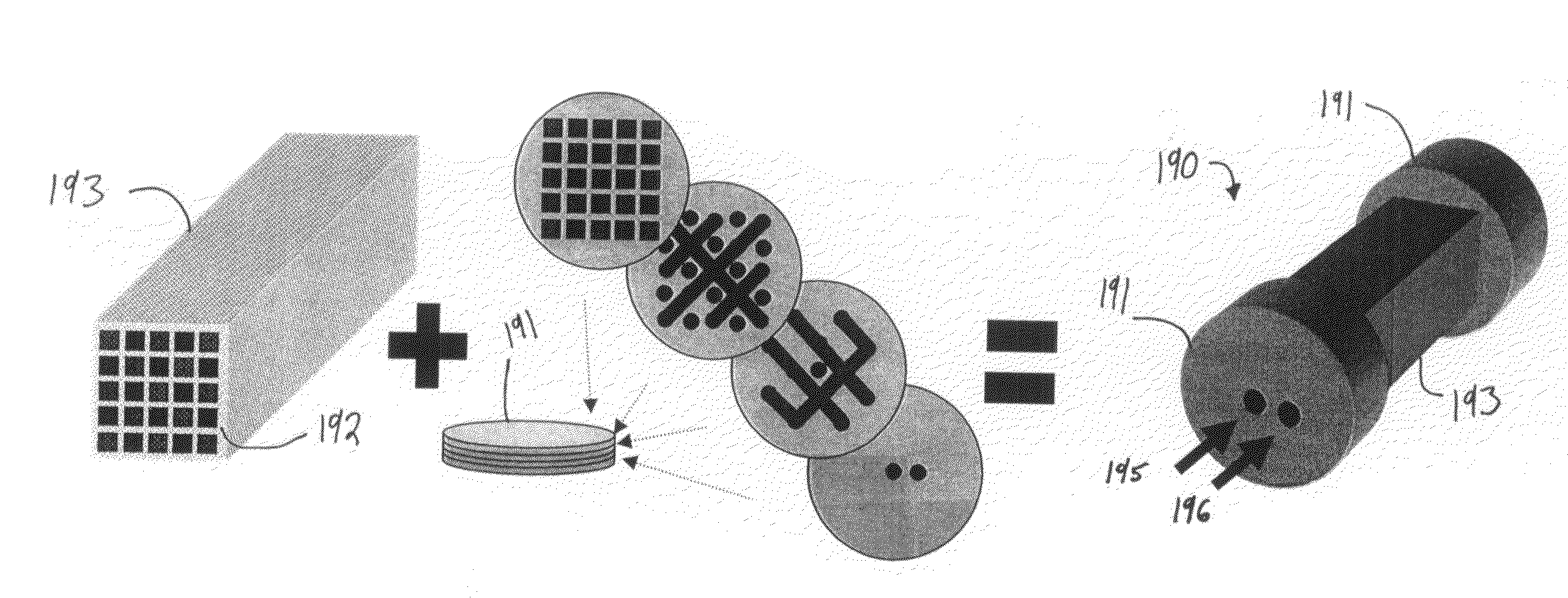
[0021]The present disclosure also provides for a method of extracting hydrogen from a fuel, wherein the step of operating the chemical reactor to produce the two-dimensional radial distribution of fluidic flow through the first, second, and third elongate chambers with respect to the first, second, and third process feeds is further for extracting a quantity of hydrogen from a gas cleanup feed, the gas cleanup feed being the other one of the first and second process feeds, and increasing a purity of a carbon dioxide effluent associated with the gas cleanup feed.

Problems solved by technology

However, efficient, portable, and robust conversion of fuels (e.g., liquid fuels, diesel fuels, logistics fuels, naval logistics fuels, etc.) to hydrogen for subsequent electrochemical conversion remains an important challenge to realizing next-generation fuel cell energy systems.
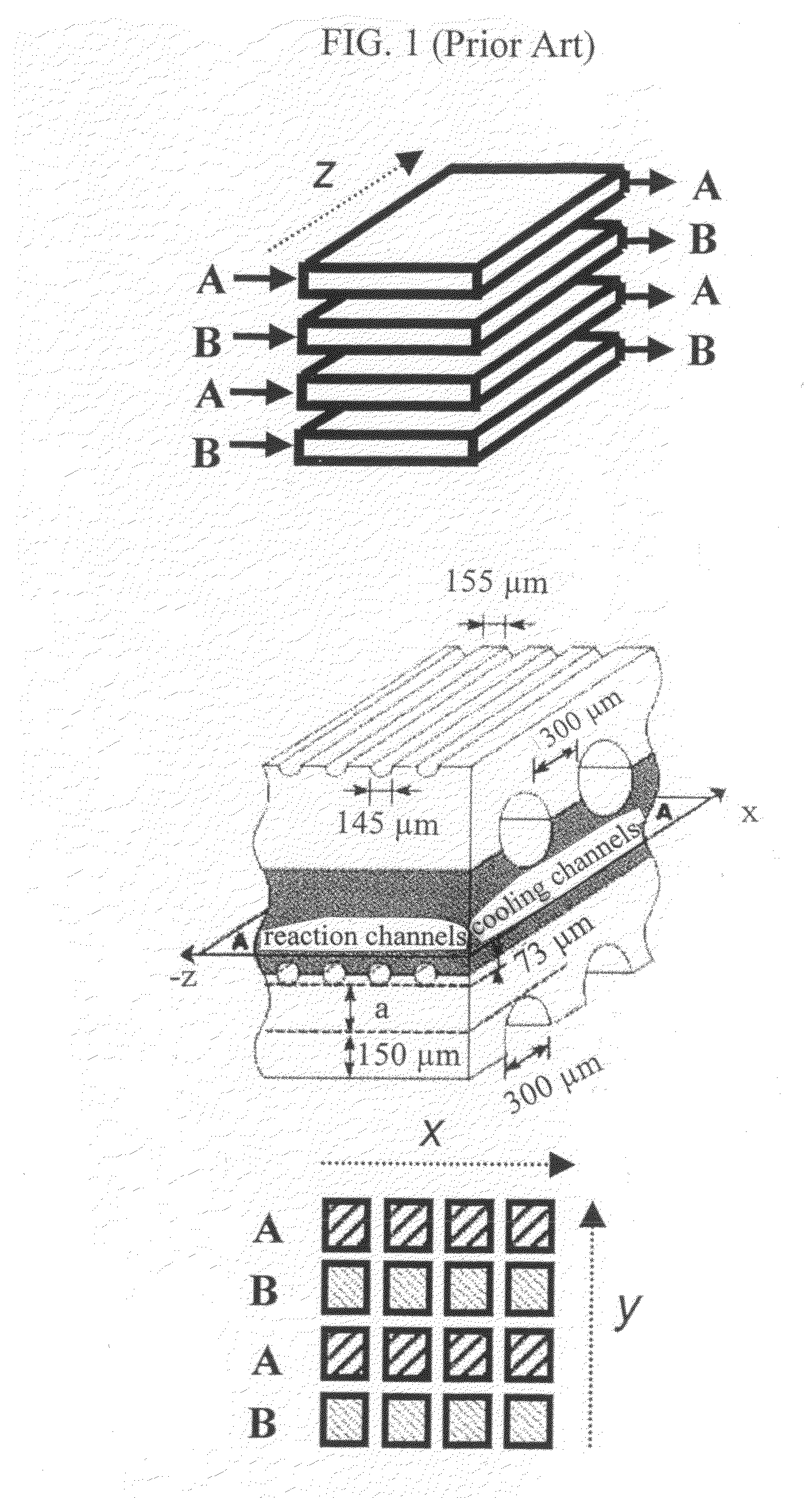
In general, current micro-fabrication methods can limit the potential for heat integration and process intensification.
In addition, one-dimensional analysis demonstrates that the use of high thermal conductivity materials (e.g., silicon, stainless steel) in such applications can significantly limit the thermal efficiency of the necessary heat exchange owing to significant axial conduction losses (see, e.g., Stief, T., O.-U.
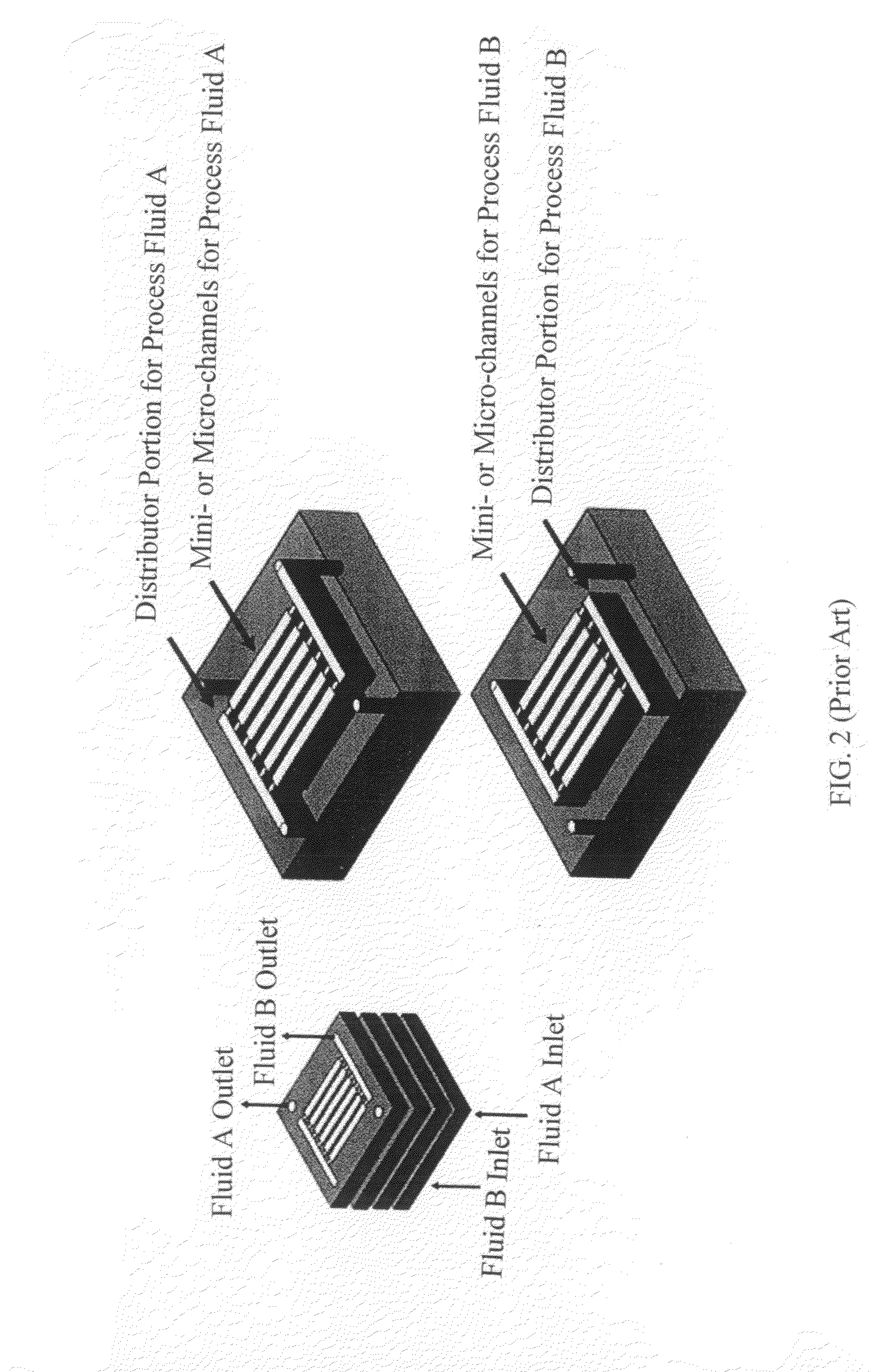
The cost of system scale-up is typically linear, as more plates are required for more channels to accommodate more or different process flows.
As practical experience dictates that stacking of more than ten (10) plates is impractical, such systems typically manifest a limited scale.
As such, micro-chemical systems have typically been limited to alternating plate designs manifesting one-dimensional radial distribution patterns of fluidic flow.
In addition, the industrial applicability of such systems is further limited by the low mechanical strength and high cost of micromachining individual porous membrane supports.

Method used


Image

  • Process Intensification In Microreactors
  • Process Intensification In Microreactors
  • Process Intensification In Microreactors

Examples


example 1

All-in-One Hydrogen Extraction from Ethanol

[0092]In accordance with exemplary embodiments of the present disclosure, coupling of multiple membrane processes and catalytic reforming steps within a single unit was demonstrated, such that the overall system efficiency, portability and cost-effectiveness was increased substantially. The extraction of pure hydrogen gas from ethanol was accomplished in accordance with embodiments of the present disclosure by coupling multiple stage-wise catalytic membrane purification processes within a single structure. Composite membranes which included a dense palladium perm-selective film coated with a porous catalytic washcoat was employed for each stage of hydrogen extraction. For example, sufficient catalyst washcoat thicknesses ensure that corrosives are destroyed before reaching the palladium surface. As shown in FIGS. 21A-B, the system couples (i) catalytic steam reforming membranes in series with (ii) water-gas-shift membranes to extract hydrog...

example 2

All-in-One Hydrogen Extraction from Diesel

[0116]Reforming of logistics fuels to hydrogen for subsequent utilization in a fuel cell system in accordance with embodiments of the present disclosure includes multiple physical and chemical processes, including, without limitation, fuel vaporization, contaminant removal and high-temperature reforming stages. The need for autothermal operation (in the absence of external heat addition, typical of portable applications) generally requires additional exothermic reactions (e.g., combustion) to provide sufficient heat to maintain required reforming temperatures and supply vaporization heat. The mini- or micro-channel networks (e.g., ceramic mini- or micro-channel networks) described herein provide powerful tools for coupling all of these separate transport and kinetic processes within one single cartridge-based, highly efficient, reforming unit.

[0117]In exemplary embodiments, the present disclosure provides for an all-in-one hydrogen-from-dies...


PUM

PropertyMeasurementUnit
temperaturesaaaaaaaaaa
thicknessesaaaaaaaaaa

Abstract

The present disclosure provides for a chemical reactor which includes elongate chambers defining an arrangement and including first, second, and third elongate chambers adapted to support respective distinct first, second, and third reactor functions associated with respective first, second, and third process feeds, and a distributor arranged in fluidic communication with each of the elongate chambers and for connecting the elongate chambers to at least one fluid source. The distributor is dimensioned to produce a two-dimensional radial distribution of fluidic flow through the first, second, and third elongate chambers with respect to the first, second, and third process feeds. The chemical reactor may further include a monolith catalyst support including an N×M array of channels including the elongated chambers. The elongate chambers and the distributor may manifest an interchangeable cartridge-based system wherein the arrangement of the elongate chambers is selectably detachable from the distributor and replaceable.

Description

RELATED FEDERALLY SPONSORED RESEARCH[0001]The work described in this patent disclosure was sponsored by the following federal agencies: National Science Foundation (NSF) Award / Grant No. 0730820 and Office of Naval Research (Young Investigator Program) Award / Grant No. N000140710828.BACKGROUND[0002]1. Technical Field[0003]The present disclosure is directed to devices, systems and methods for catalyzing chemical reactions. More particularly, the present disclosure is directed to devices, systems, and methods for catalyzing chemical reactions via the use of dedicated reactors and / or micro-chemical systems.[0004]2. Background Art[0005]In general, fuel cell systems (e.g., systems employing electrochemical combustion of hydrogen gas) promise high-power, high-efficiency systems for meeting future propulsion and energy needs. For example, by utilizing electrochemical combustion of hydrogen gas, these systems generally overcome Carnot-cycle efficiency losses inherent to conventional direct-co...

Claims


Application Information

Patent Timeline
Patent Type & Authority Applications(United States)
IPC IPC(8): C01B3/02B01J10/00B01J16/00B01J19/02
CPCB01J19/2485C01B2203/86C01B3/34C01B2203/0233C01B2203/0244C01B2203/0261C01B2203/0283C01B2203/041C01B2203/044C01B2203/047C01B2203/066C01B2203/0811C01B2203/1023C01B2203/1035C01B2203/1047C01B2203/107C01B2203/1217C01B2203/1223C01B2203/1229C01B2203/1247C01B2203/1258C01B3/32Y02P30/00B01D71/0271
Inventor WILHITE, BENJAMIN A.MORENO, ANGELA M.KIM, DAEJIN
Owner UNIV OF CONNECTICUT
Learn More