

Simulation apparatus, simulation method, and program
- Summary
- Abstract
- Description
- Claims
- Application Information
AI Technical Summary
Problems solved by technology
Method used
Image

Examples
first embodiment
[0045]FIG. 13 is a block diagram illustrating an example of a configuration of a computer included in the simulation apparatus according to aspects in accordance with a first embodiment. The computer can generate RTL design data and net list design data by computer-aided design (CAD), and perform simulation.
[0046]To a bus 1301, a central processing unit (CPU) 1302, a read-only memory (ROM) 1303, a random access memory (RAM) 1304, a network interface 1305, an input device 1306, an output device 1307, and an external storage device 1308 are connected.
[0047]The CPU 1302 performs processing of data and calculation, and controls the above-described configuration unit that is connected via the bus 1301. In the ROM 1303, a boot program is stored in advance. By implementing the boot program by the CPU 1302, the computer is started up. In the external storage device 1308, a computer program is stored. The computer program is copied into the RAM 1304, and the program is implemented by the CPU...
second embodiment
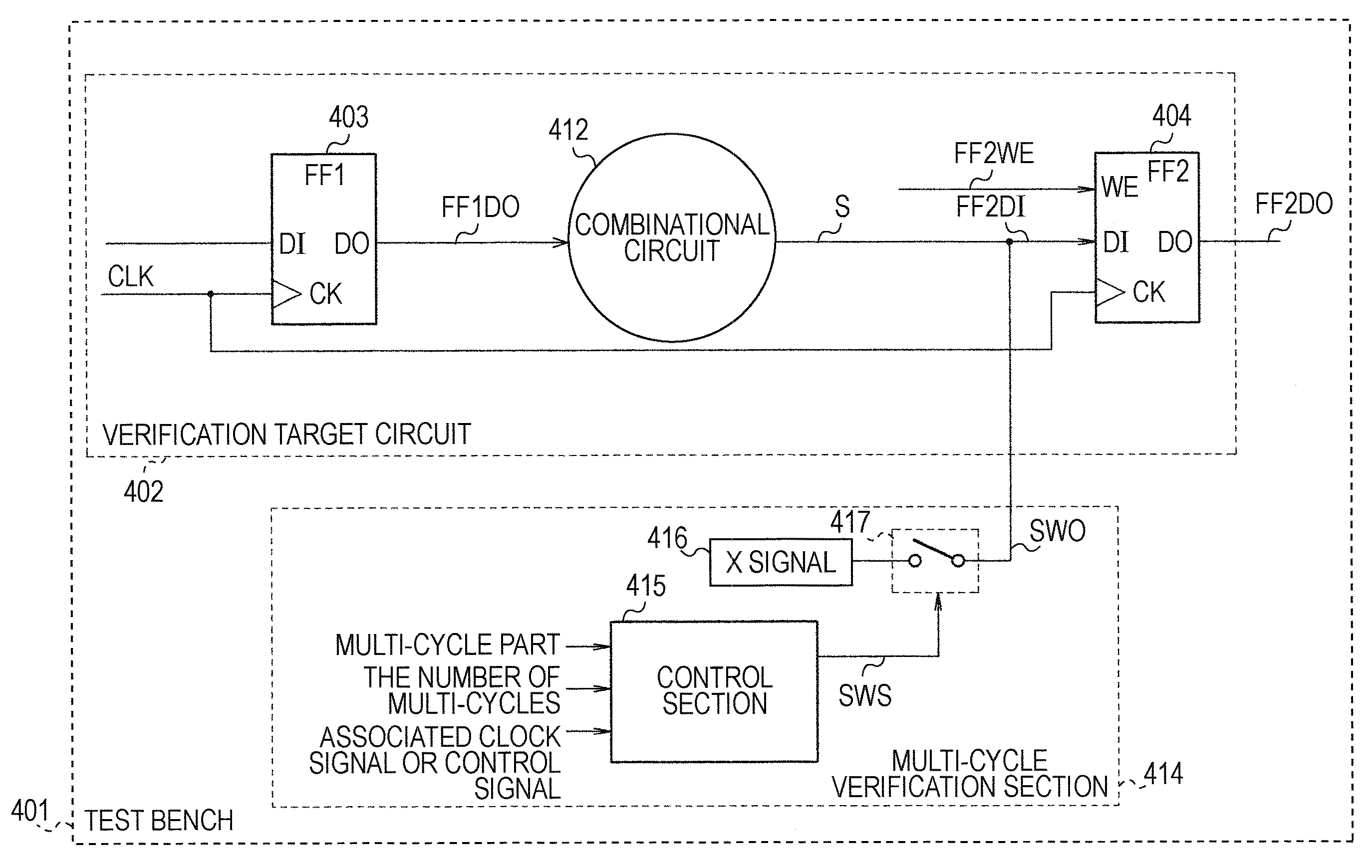
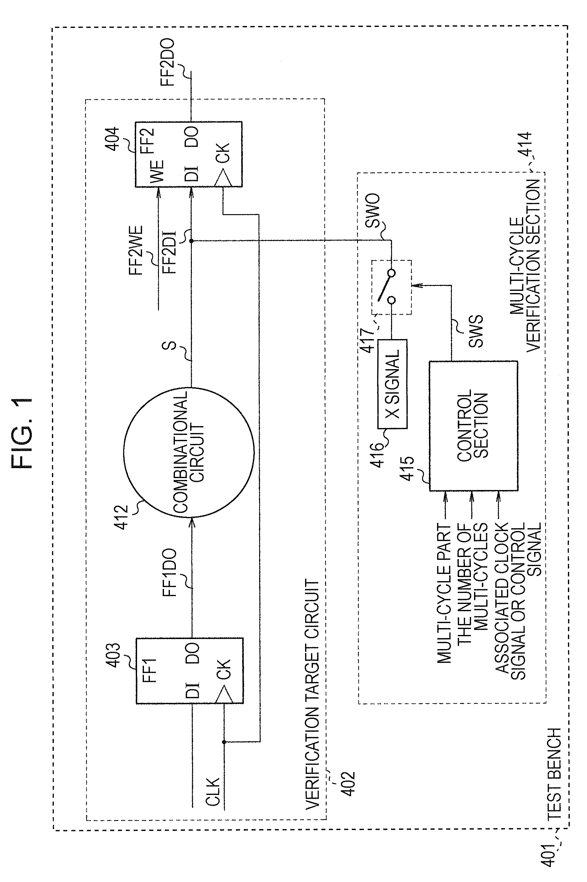
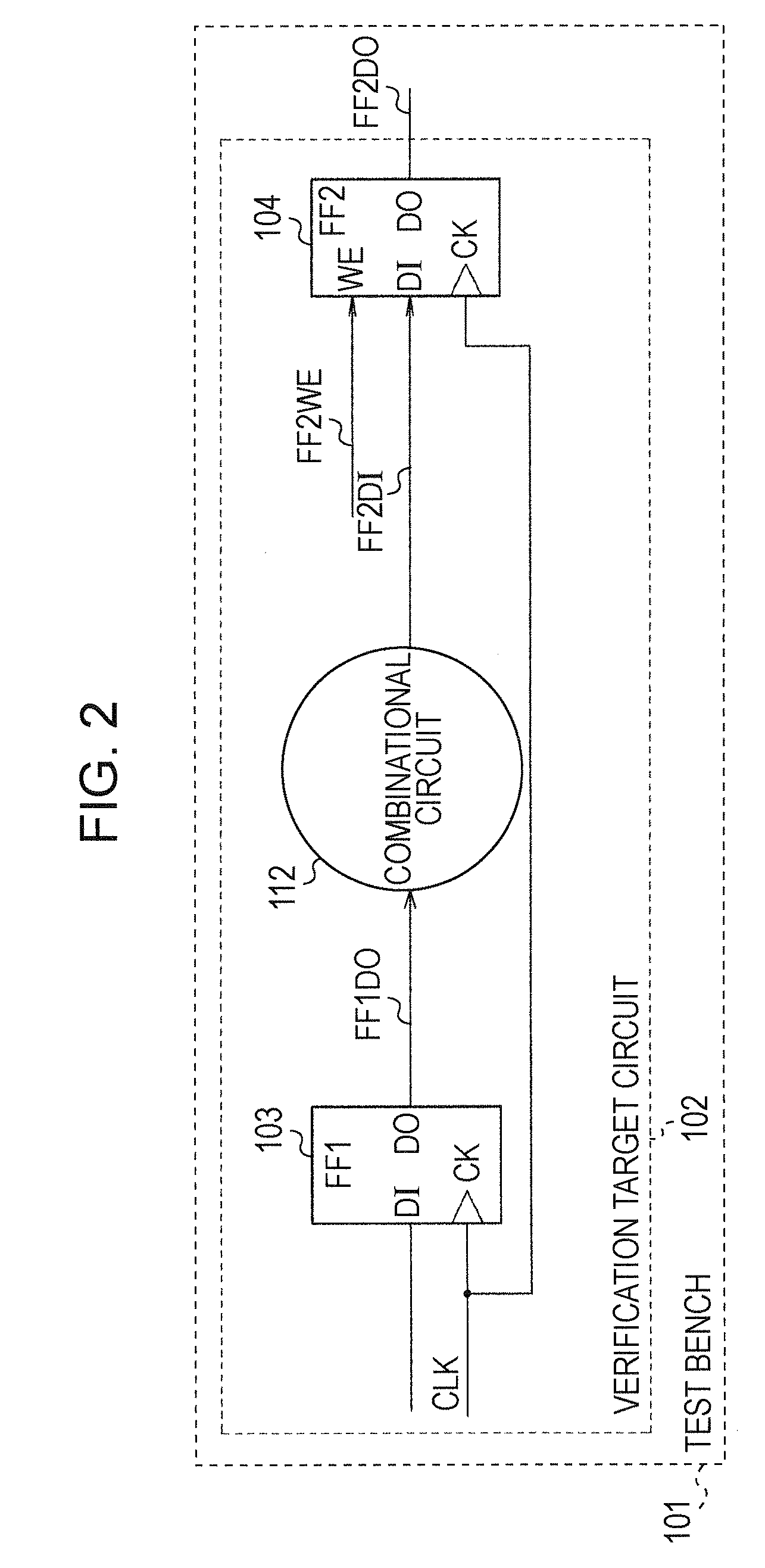
[0077]FIG. 7 is a schematic view illustrating a test bench of a simulation apparatus according to aspects of a second embodiment. In the second embodiment (FIG. 7), aspects are similar to the first embodiment (FIG. 1). Hereinafter, only the differences for the second embodiment are described.
[0078]In aspects of the second embodiment, when the test bench 401 is installed in the simulation apparatus, the signal S and the signal FF2DI are disconnected. The signal S is transmitted to the signal FF2DI via the multi-cycle verification section 414. After simulation is completed, the multi-cycle verification section 414 is deleted, and the signal S is directly connected to the signal FF2DI by a signal line 725.
[0079]The multi-cycle verification section 414 includes a signal variation observation section 715 that observes variation of the signal S, a counter CNT that calculates the number of cycles to drive an X signal on the basis of the number of multi-cycles N, an X signal output section ...
third embodiment
[0091]FIG. 10 is a schematic view illustrating a test bench of a simulation apparatus according to aspects of a third embodiment. In the third embodiment (FIG. 10), similar to the first embodiment (FIG. 1), a specific example of the multi-cycle verification section 414 is described. Hereinafter, only the different points of the third embodiment are described.
[0092]The multi-cycle verification section 414 includes an X signal output section 1016, an a switch SW. The X signal output section 1016 outputs an X signal. A write enable signal FF2WE is a control signal that shows valid or invalid of writing of an input signal FF2DI into the second flip-flop 404. The switch SW, depending on the write enable signal FF2WE, connects or disconnects a terminal of an output signal of the X signal output section 1016 and a terminal of the signal FF2DI.
[0093]The use of the write enable signal FF2WE as the control signal of the switch SW is one of the simplest simulation methods for enabling the sign...
PUM
 Abstract
Description
Claims
Application Information