Method and apparatus for matrix decomposition in programmable logic devices

a programmable logic device and matrix decomposition technology, applied in the field of method and apparatus for matrix decomposition, can solve the problem of prohibitively expensive complexity of calculating the optimum solution afresh for each iteration

Inactive Publication Date: 2009-09-24
ALTERA CORP
View PDF2 Cites 29 Cited by
  • Summary
  • Abstract
  • Description
  • Claims
  • Application Information

AI Technical Summary

Problems solved by technology

Calculating the optimum solution afresh for each iteration is prohibitively expensive in terms of complexity, as each calculation is O(N3), that is, it requires a number of individual calculations that varies with the cube of N. However, it is possible to update the matrix decomposition in O(N2) operations.

Method used


Image

  • Method and apparatus for matrix decomposition in programmable logic devices
  • Method and apparatus for matrix decomposition in programmable logic devices
  • Method and apparatus for matrix decomposition in programmable logic devices

Examples


Embodiment Construction

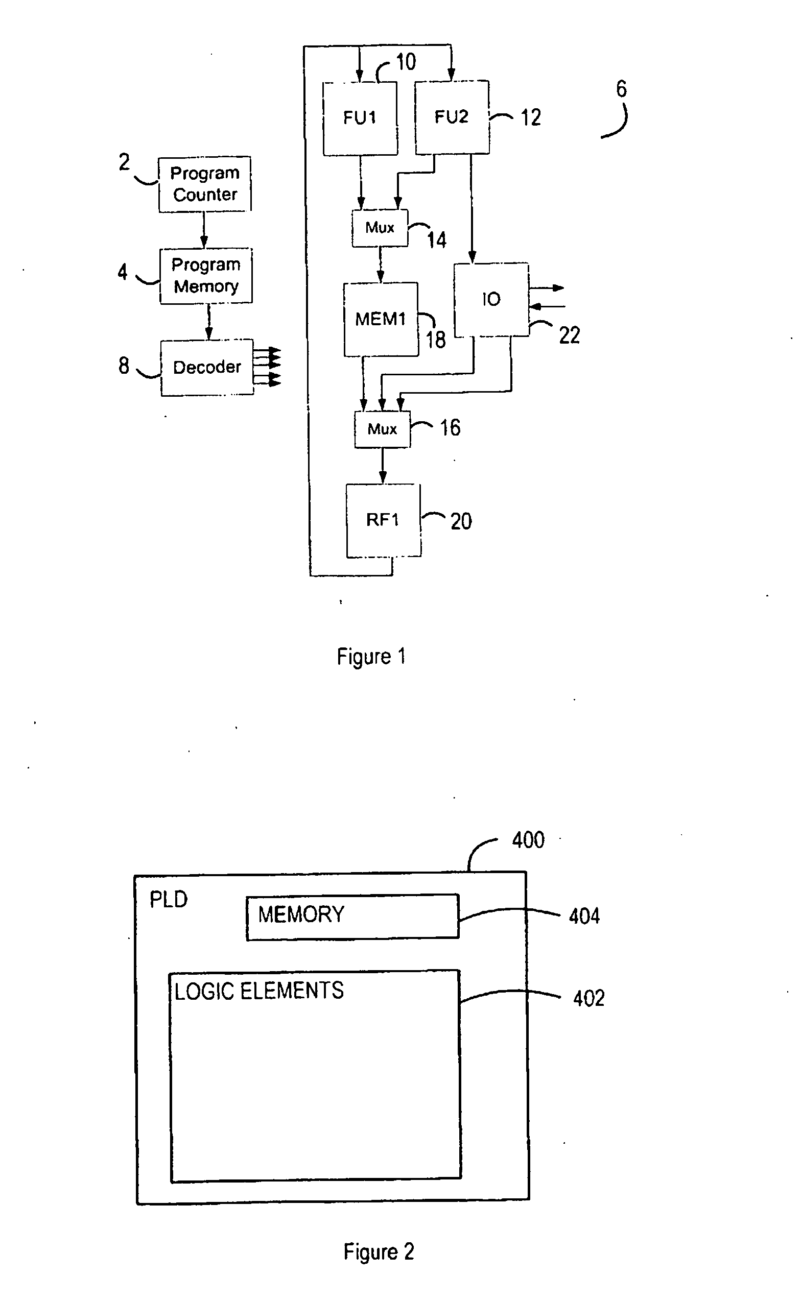
[0040]FIG. 1 shows the general form of an FPGA-based application-specific integrated processor (ASIP). A pipelined program memory 2 and program counter 4 supply the machine with an encoded instruction word. The program memory 2 is typically included within the processor 6 and exploits the dual-port facilities of the memories to allow external sources to load program code.

[0041]The encoded instruction word feeds a decode block 8 that decodes the data to provide a set of control signals for the processor 6. Control signals include: immediate values such as literals, register file read and write addresses; function unit enable and operation select signals; multiplexer operand-select codes.

[0042]The processing core 6 includes a set of function units 10, 12 and the multiplexers 14, 16 that route data between them. The function units include memories 18, registers, basic arithmetic and logic units, and multiply-add blocks. These blocks may exploit specific features of the FPGA device or m...


PUM


Abstract

A processor is adapted for performing a QR-decomposition. The processor has a program memory, a program controller, connected to the program memory to receive program instructions, and at least one processing unit. The processing unit includes a CORDIC calculation block, and has a distributed memory structure, with separate memory blocks for storing respective parameter values.

Description

[0001]This invention relates to a method and apparatus for matrix decomposition, more specifically for implementation of OR-decomposition (QRD) and recursive least squares (RLS) based QRD, and in particular to an architecture that is suitable for implementation in an FPGA (field programmable gate array).[0002]In many areas of technology, for example in specific areas of signal processing such as wireless communications or image processing, it is necessary to solve problems in linear algebra. One well-known technique for solving such problems is to use the QR-decomposition (QRD)-based recursive least squares (RLS) algorithm.[0003]QR-decomposition is a well-accepted technique employed in matrix calculations. A matrix A is decomposed into Q and R:A=Q·R [0004]Where R is an upper triangular matrix and Q is an orthogonal matrix, that is:QT·Q=1[0005]In this example, Q is formed of a sequence of Givens rotations, each designed to annihilate a particular element of the matrix A.[0006]QR-deco...

Claims


Application Information

Patent Timeline
Patent Type & Authority Applications(United States)
IPC IPC(8): G06F15/76G06F9/06
CPCG06F17/16G06F7/60G06F17/00
Inventor FITTON, MICHAEL
Owner ALTERA CORP
Why Eureka
Try Eureka