

Regeneration of Diesel Particulate Filters
a technology of particulate filter and diesel, which is applied in the direction of machines/engines, mechanical equipment, electric control, etc., can solve the problems of large amounts of soot igniting simultaneously, and achieve the effect of effectively controlling the subsequent combustion process and reducing thermal conductivity
- Summary
- Abstract
- Description
- Claims
- Application Information
AI Technical Summary
Benefits of technology
Problems solved by technology
Method used
Image

Examples
Embodiment Construction
[0032]An important advantage of the invention is that various highly efficient filter construction materials, including porous cordierite ceramics, that are less refractory than non-oxide filter materials and which have heretofore been considered to present a somewhat higher risk of regeneration damage at high soot loadings, can be more widely and economically employed if heating ramp rates in accordance with the invention are used for filter regeneration. Another advantage is that, regardless of the filter construction material employed, the intervals between filter regenerations, (which regenerations typically impose measurable fuel consumption penalties) can be increased. This is because regenerations at higher filter loadings of combustible particulates can be successfully managed.
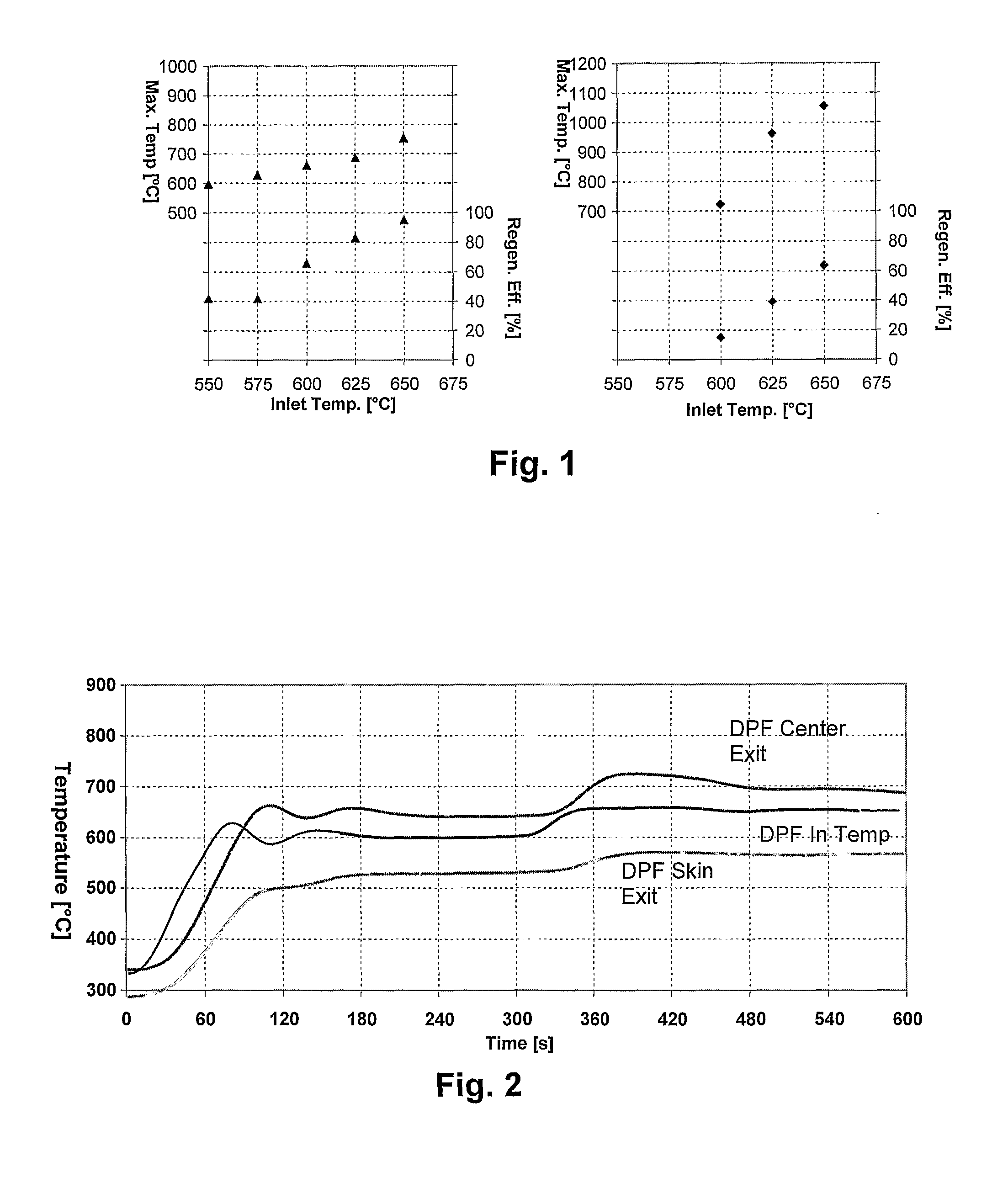
[0033]Filter performance maps to control DPF regeneration cycles for any particular filter design and construction as well as for any engine and designed regeneration initiation system can be developed...
PUM
| Property | Measurement | Unit |
|---|---|---|
| temperature | aaaaa | aaaaa |
| temperature | aaaaa | aaaaa |
| temperatures | aaaaa | aaaaa |
Abstract
Description
Claims
Application Information