Rotating electric machine

a technology of rotating electric machines and electric motors, which is applied in the direction of windings, dynamo-electric components, and magnetic circuit shapes/forms/constructions, etc., can solve the problems of large electromagnetic noise of harmonics, large disturbance of rider in vehicles, and increase in electric noise generated during driving, so as to reduce electromagnetic noise, suppress stator vibration, and increase magnetic resistance

Active Publication Date: 2009-10-01
TOYOTA JIDOSHA KK
View PDF2 Cites 23 Cited by
  • Summary
  • Abstract
  • Description
  • Claims
  • Application Information

AI Technical Summary

Benefits of technology

[0021]By increasing the magnetic resistance of the tooth portion in the rotating electric machine, the magnetic resistance of the magnetic circuit formed at the different-phase-intermediate tooth becomes larger than the magnetic resistance of the magnetic circuit formed at the same-phase-intermediate tooth. Accordingly, by acquiring balance between the number of flux linkages of the different-phase-intermediate tooth reduced as a result of the increased magnetic resistance and the number of flux linkages of the same-phase-intermediate tooth, the electromagnetic excitation applied thereto is equalized.
[0022]By acquiring balance in the number of flux linkages between the same-phase-intermediate tooth and different-phase-intermediate tooth in the present invention, the electromagnetic excitation of the same-phase-intermediate tooth and the electromagnetic excitation of the different-phase-intermediate tooth applied in directions opposite to each other along the radial direction are equalized. Since the electromagnetic excitation of the same-phase-intermediate tooth and the electromagnetic excitation of the different-phase-intermediate tooth cancel each other, the electromagnetic excitation applied to the stator in entirety is substantially zero. As a result, stator vibration is suppressed, allowing reduction in the electromagnetic noise.

Problems solved by technology

There was a problem that the electromagnetic noise generated during driving will become so great that the rider in the vehicle will be disturbed by the noise.
Recently, it has become apparent that this electromagnetic noise of harmonics is greatly affected by the electromagnetic excitation of 6f generated during motor operation.
However, the AC rotating electric machine for a vehicle disclosed in Japanese Patent Laying-Open No. 2003-348781 encounters the problem that the 6f electromagnetic excitation cannot be reliably reduced due to the uneven magnetic flux generated at the stator iron core among the plurality of stator teeth in response to the supply of the alternating current to the wound 3-phase stator coil.
Therefore, there is an imbalance in the number of windings of the stator coil between the stator teeth corresponding to the first slot group, having the first stator coil wound, and the stator teeth corresponding to the second slot group, having the second stator coil wound.
The radial vibration occurring at the stator core due to the imbalance of the component in the radial direction causes the air in contact with the outer circumferential face or inner circumferential face of the stator core to vibrate, leading to the generation of a large electromagnetic noise.

Method used


Image

  • Rotating electric machine
  • Rotating electric machine
  • Rotating electric machine

Examples


first embodiment

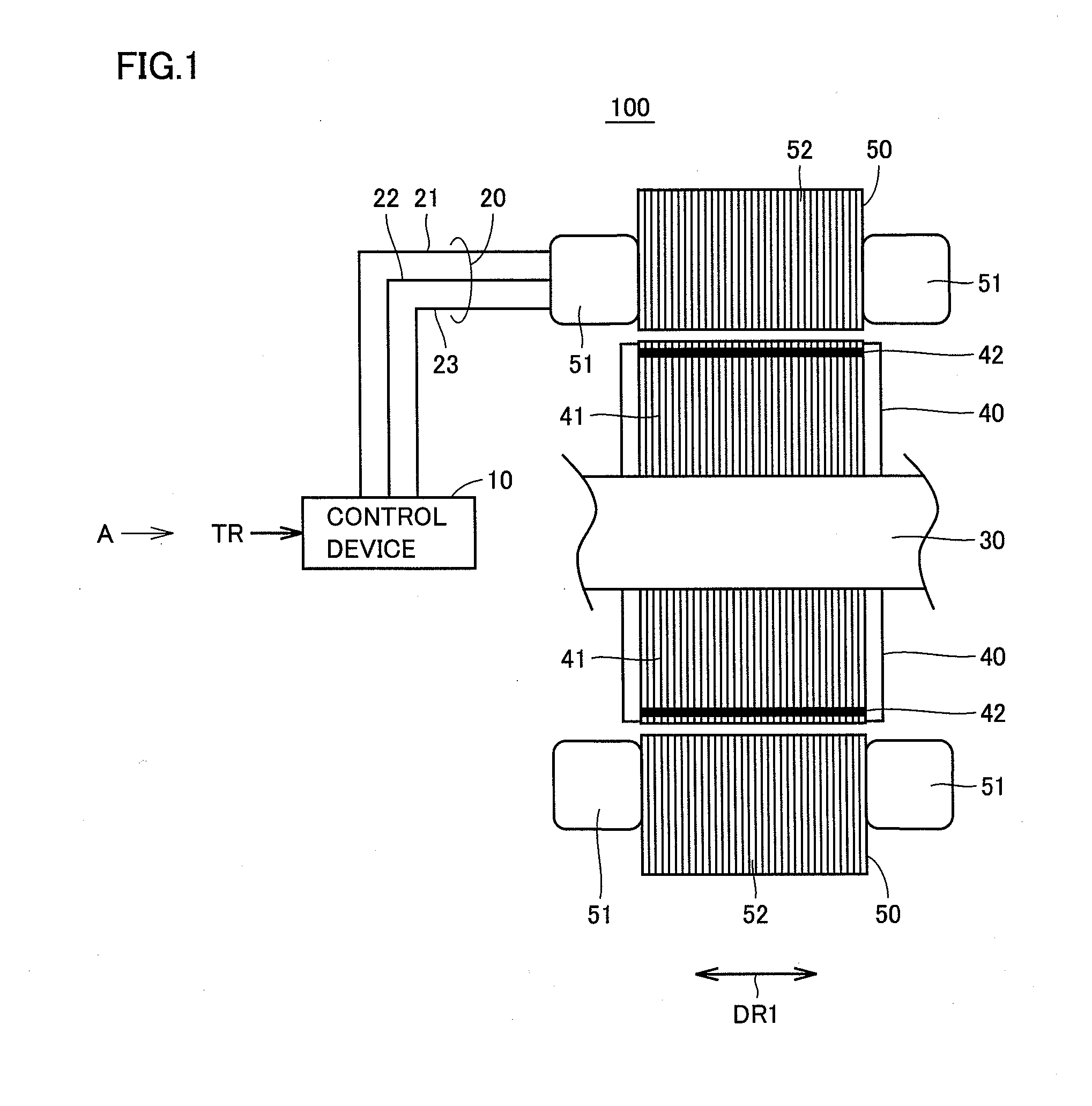
[0035]FIG. 1 is a sectional view of a rotating electric machine according to a first embodiment of the present invention.

[0036]Referring to FIG. 1, a rotating electric machine 100 of the present invention includes a control device 10, a 3-phase cable 20, a shaft 30, a rotor 40, and a stator 50.

[0037]Rotor 40 includes a rotor core 41 and a magnet 42. Stator 50 includes a stator coil 51, and a stator core 52.

[0038]Control device 10 receives a torque control value TR to be output by rotating electric machine 100 from an ECU (Electrical Control Unit) provided external to rotating electric machine 100 to generate a motor control current MCTLI for providing torque according to the receive torque control value TR, and provides the generated motor control current MCTLI to stator coil 51 of stator 50 via 3-phase cable 20.

[0039]3-phase cable 20 connects control device 10 and stator coil 51. 3-phase cable 20 includes a U-phase cable 21, a V-phase cable 22, and a W-phase cable 23. Shaft 30 is i...

second embodiment

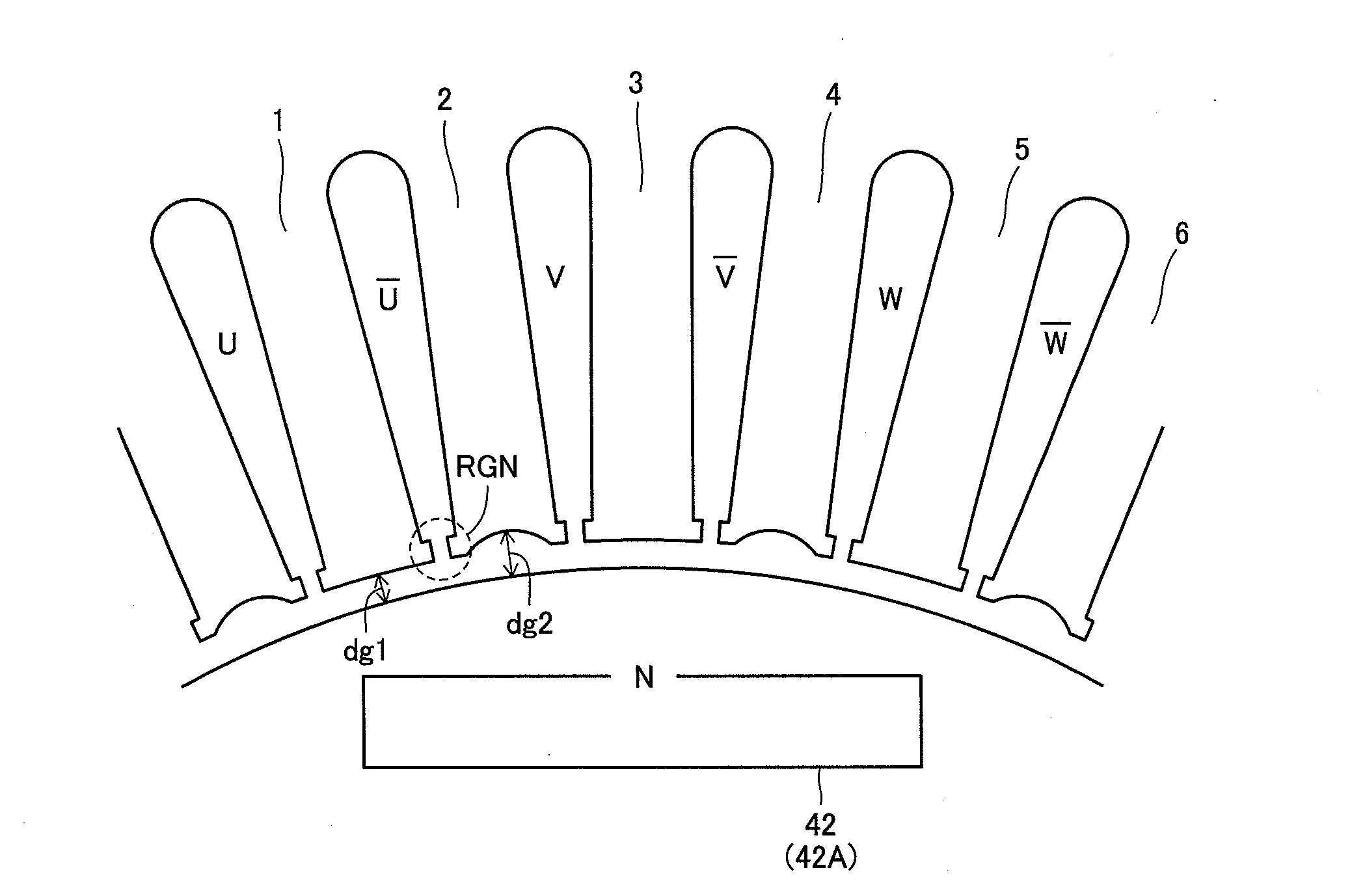
[0093]FIG. 11 is a diagram to describe a stator core of a rotating electric machine according to a second embodiment of the present invention.

[0094]Referring to FIG. 11, stator core 52B is configured such that the tooth length in the circumferential direction differ between same-phase-intermediate tooth 1 (or 3, 5) and different-phase-intermediate tooth 2 (or 4, 6). Specifically, the teeth are formed such that the length of different-phase-intermediate tooth 2 in the circumferential direction (corresponding to 12 in the drawing) is larger than the length of same-phase-intermediate tooth 1 in the circumferential direction (corresponding to 11 in the drawing). Since the length of each tooth in the direction of the rotational shaft is equal, the cross sectional area of different-phase-intermediate tooth 2 is smaller than the cross sectional area of same-phase-intermediate tooth 1.

[0095]In view of the magnetic resistance of the teeth region being in inverse proportion to the cross secti...


PUM


Abstract

In a rotating electric machine that is formed of a distribution winding motor with two slots per each pole and each phase, a stator core includes an air gap of a constant width dg1 between the leading end of a same-phase-intermediate tooth and the outer circumferential face of a rotor core, and an air gap of a width not uniform in the circumferential direction between the leading end of a different-phase-intermediate tooth and the outer circumferential face of the rotor core, with a width dg2 (>dg1) as the largest value. A magnetic circuit having a magnetic resistance higher than that of the same-phase-intermediate tooth is formed at the different-phase-intermediate tooth. By establishing a difference in the width of the air gap such that the number of flux linkages at the different-phase-intermediate tooth reduced by the increased magnetic resistance is substantially equal to the number of flux linkages at the same-phase-intermediate tooth, the electromagnetic excitation applied in directions opposite to each other acquire balance so as to cancel each other, allowing vibration at the stator core to be suppressed.

Description

TECHNICAL FIELD[0001]The present invention relates to rotating electric machines, particularly a rotating electric machine allowing reduction in electromagnetic noise.BACKGROUND ART[0002]Recently, attention is focused on hybrid vehicles and electric vehicles as vehicles taking into account environmental issues. A hybrid vehicle includes, in addition to a conventional engine, a direct current power source, an inverter, and a rotating electric machine (motor) driven by the inverter as the power source. In addition to achieving the power source by driving the engine, the direct current voltage from the direct current power source is converted into alternating voltage by the inverter, and the converted alternating voltage is used to rotate the motor to achieve power.[0003]An electric vehicle includes a direct current power source, an inverter, and a motor driven by the inverter as the power source.[0004]In such a hybrid vehicle or electric vehicle, the motor is driven in a relatively wi...

Claims


Application Information

Patent Timeline
Patent Type & Authority Applications(United States)
IPC IPC(8): H02K1/16
CPCH02K1/165H02K29/03H02K3/28H02K1/06H02K3/12
Inventor HATTORI, HIROYUKI
Owner TOYOTA JIDOSHA KK
Why Eureka
Try Eureka