Method of forming carbon film, method of manufacturing magnetic recording medium, and apparatus for forming carbon film

a carbon film and magnetic recording medium technology, applied in the direction of electrical equipment, chemical vapor deposition coatings, coatings, etc., can solve the problem of lowering the coverage over the surface of the insufficient durability of the carbon film, and the tribology problem between the magnetic head and the magnetic recording medium, so as to reduce the distance between the magnetic recording medium and the magnetic head. , the effect of reducing the thickness of the carbon film

Inactive Publication Date: 2010-02-04
SHOWA DENKO HD SINGAPORE PTE
View PDF3 Cites 40 Cited by
  • Summary
  • Abstract
  • Description
  • Claims
  • Application Information

AI Technical Summary

Benefits of technology

[0024]According to the present invention, it is possible to form a dense carbon film with high hardness. For example, when the carbon film is used as a protective film of a magnetic recording medium, it is possible to reduce the thickness of the carbon film and thus reduce the distance between the magnetic recording medium and the magnetic head. As a result, it is possible to increase the recording density of the magnetic recording medium and increase the corrosion resistance of the magnetic recording medium.

Problems solved by technology

Therefore, in recent years, the tribology problem between the magnetic head and the magnetic recording medium has become the key technical problem which needs to be solved.
Among these methods, when the carbon film is formed with a thickness of, for example, 100 Å or less by the sputtering method, the durability of the carbon film is likely to be insufficient.
When the carbon film formed by the CVD method has low flatness and a small thickness, the coverage over the surface of the magnetic recording medium is lowered, and the magnetic recording medium is likely to corrode.
However, there are limitations in the method.
In addition, when the anode current is excessively large, an abnormal discharge occurs in an excitation space, which causes the thickness of the formed carbon film to be non-uniform or the filament to break.
When the temperature of the filament is excessively high, there is a concern that the filament will break, or the filament material will be evaporated and mixed with the carbon film.

Method used


Image

  • Method of forming carbon film, method of manufacturing magnetic recording medium, and apparatus for forming carbon film
  • Method of forming carbon film, method of manufacturing magnetic recording medium, and apparatus for forming carbon film
  • Method of forming carbon film, method of manufacturing magnetic recording medium, and apparatus for forming carbon film

Examples


example 1

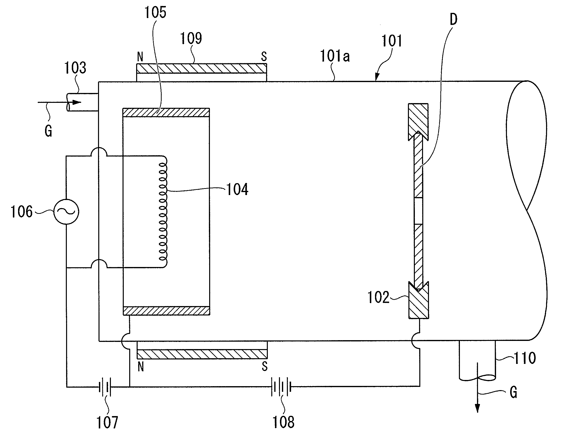
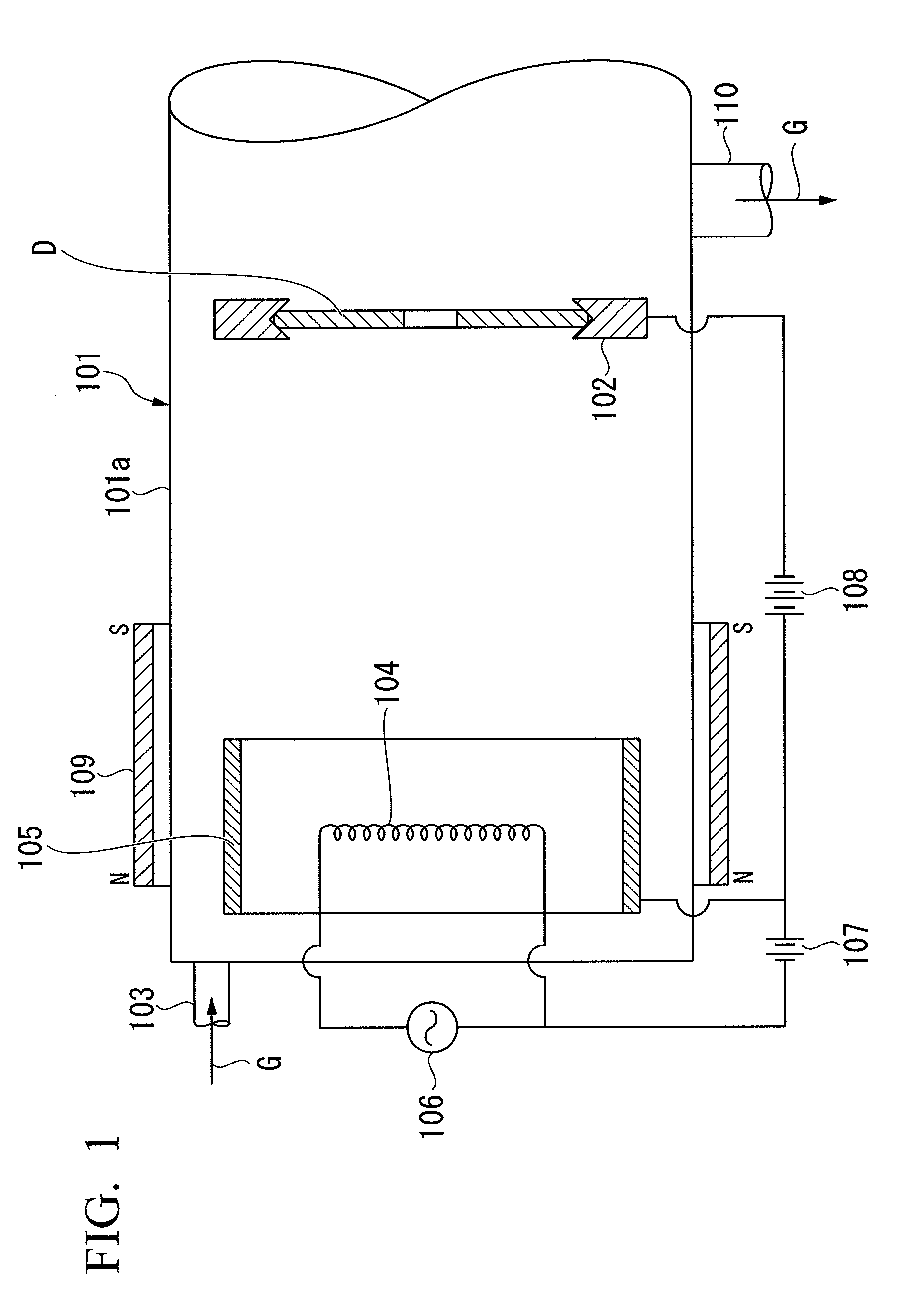
[0088]In Example 1, first, an aluminum substrate plated with NiP was prepared as a non-magnetic substrate. Then, the in-line film forming apparatus shown in FIG. 6 was used to sequentially form soft magnetic layers that were made of FeCoB and had a thickness of 60 nm, intermediate layers that were made of Ru and had a thickness of 10 nm, and recording magnetic layers that were made of a 70Co-5Cr-15Pt-10SiO2 alloy and had a thickness of 15 nm, thereby forming magnetic layers on both surfaces of the non-magnetic substrate that was mounted on a carrier made of A5052 aluminum alloy. Then, the non-magnetic substrate mounted on the carrier was transported into a processing chamber having the same apparatus structure as that of the film forming apparatus shown in FIG. 1, and protective layers, which were carbon films, were formed on both surfaces of the non-magnetic substrate having the magnetic layers formed thereon.

[0089]Specifically, the processing chamber had a cylindrical shape with a...

examples 2 and 3

[0091]In Example 2, a magnetic recording medium was manufactured under the same conditions as those in Example 1 except that the carbon film was formed with a thickness of 3 nm. In Example 3, a magnetic recording medium was manufactured under the same conditions as those in Example 1 except that the carbon film was formed with a thickness of 2.5 nm.


PUM

PropertyMeasurementUnit
diameteraaaaaaaaaa
currentaaaaaaaaaa
voltageaaaaaaaaaa

Abstract

The present invention provides a carbon film forming method capable of forming a dense carbon film with high hardness. The carbon film forming method includes: introducing a raw material gas G including carbon into a deposition chamber 101 whose internal pressure is reduced; ionizing the raw material gas G using a discharge between a filament-shaped cathode electrode 104 heated by electrical power and an anode electrode 105 provided around the cathode electrode; and accelerating and radiating the ionized gas to the surface of a substrate D. A magnetic field is applied by a permanent magnet 109 to increase the ion density of the ionized gas accelerated and radiated to the surface of the substrate D. In this way, it is possible to form a carbon film with high hardness and high density on the surface of the substrate D.

Description

BACKGROUND[0001]1. Technical Field[0002]The present invention relates to a method of forming a carbon film, a method of manufacturing a magnetic recording medium, and an apparatus for forming a carbon film.[0003]Priority is claimed on Japanese Patent Application No. 2008-190066, filed Jul. 23, 2008, the content of which is incorporated herein by reference.[0004]2. Background Art[0005]In recent years, in the field of magnetic recording media used in, for example, hard disk drives (HDDs), recording density has improved significantly at a rate of about 100 times per 10 years. There are many techniques available in order to improve the recording density. One of the key technologies is to control the sliding characteristics between the magnetic head and the magnetic recording medium.[0006]For example, a CSS (contact start-stop) system, which is also called the Winchester system, in which a basic operation from the start to the end of the operating of a magnetic head including contact / sli...

Claims


Application Information

Patent Timeline
Patent Type & Authority Applications(United States)
IPC IPC(8): G11B5/84
CPCC23C16/26G11B5/8408C23C16/503
Inventor OTA, ICHIRO
Owner SHOWA DENKO HD SINGAPORE PTE
Why Eureka
Try Eureka