Filament lamp

Inactive Publication Date: 2009-10-01
USHIO DENKI KK
View PDF0 Cites 2 Cited by
  • Summary
  • Abstract
  • Description
  • Claims
  • Application Information

AI Technical Summary

Benefits of technology

[0017]In the conventional technology as described above, the metal foil on the hermetically sealed parts at both ends has a parallel structure, with electric current supplied separately to each of the adjacent sheets of metal foil 7a, 8a, and 9a. Accordingly, a prescribed gap is required between the respective metal foil sheets in order to prevent electric discharge. As a result, the dimension W increases in the perpendicular direction (width direction) relative to the axis direction of the light-emitting tube with the hermetically sealed parts 2a, 2b, and in the case of a heating device in which a plurality of filament lamps is disposed in parallel, the overall size of the device increases, which is problematic. Also, when a plurality of filament lamps is disposed in parallel, the dimension of the space between the lamps is limited by the width dimension of the hermetically sealed parts, making it impossible to dispose lamps in high density, which is problematic.

Problems solved by technology

However, at the periphery of the semiconductor wafer, temperature exchange occurs with the peripheral atmosphere, causing a tendency for the temperature to drop as compared with the center region.
Since heat is radiated from the lateral surface of the semiconductor wafer, the temperature in the peripheral region of the semiconductor wafer declines, resulting in non-uniformity of temperature distribution on the semiconductor wafer.
However, in a conventional heat treatment device, separate control in the lamp tube axis direction has not been possible for tiny specific regions that are extremely small in relation to the light-emitting length of an incandescent lamp.
As a result, if optical irradiation is performed at an irradiance attuned to the properties of that specific region, areas other than the specific region are also optically irradiated with the same conditions, making it impossible to perform temperature adjustment for the appropriate temperature conditions in the specific region and in other regions.
Consequently, the temperature of the specific region is not necessarily the same as the temperature of other regions, leading to an undesired temperature distribution of the treatment temperature on the article to be treated.
As a result, it is difficult to impart the desired physical properties to the article to be treated, which is problematic.
As a result, the dimension W increases in the perpendicular direction (width direction) relative to the axis direction of the light-emitting tube with the hermetically sealed parts 2a, 2b, and in the case of a heating device in which a plurality of filament lamps is disposed in parallel, the overall size of the device increases, which is problematic.
Also, when a plurality of filament lamps is disposed in parallel, the dimension of the space between the lamps is limited by the width dimension of the hermetically sealed parts, making it impossible to dispose lamps in high density, which is problematic.
However, in this case, the number of sheets of metal foil must also be increased in proportion, rendering the problems noted above still more serious.

Method used


Image

  • Filament lamp
  • Filament lamp
  • Filament lamp

Examples


Embodiment Construction

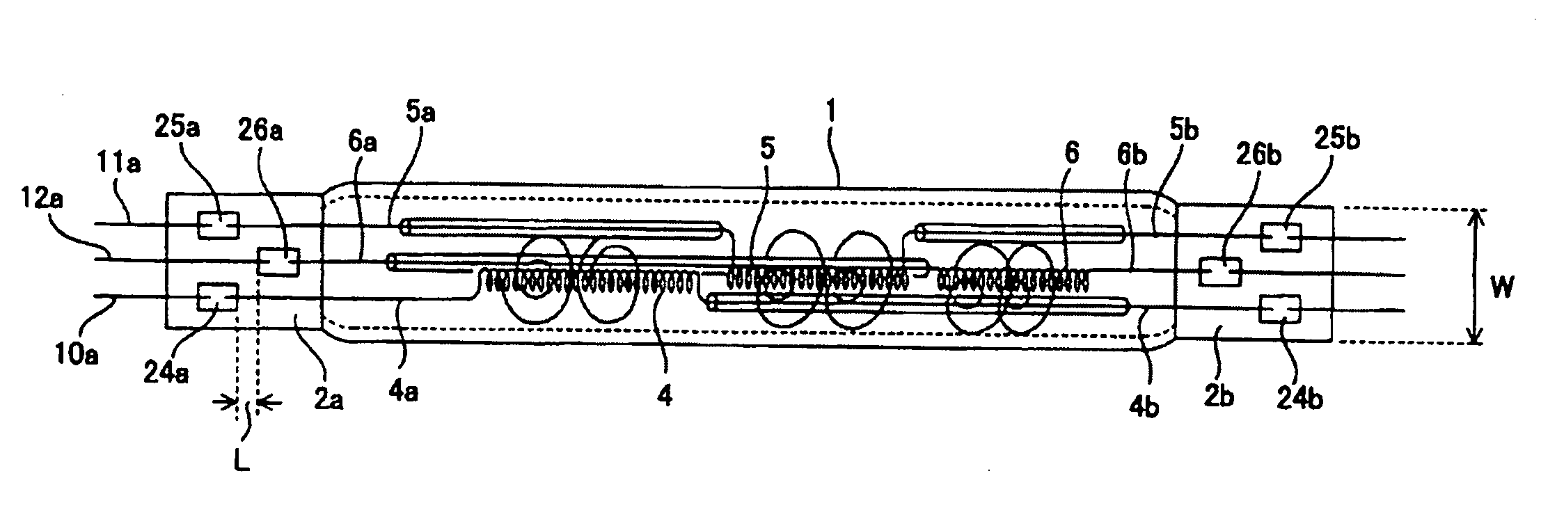
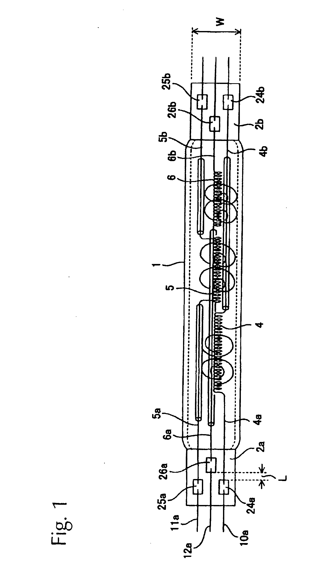
[0024]Taking note of the problems with the conventional technology described above, the present invention seeks to provide a filament lamp in which the width direction dimension of the hermetically sealed parts does not increase, even if the number of filaments, or in other words, the number of metal foil sheets, increases.

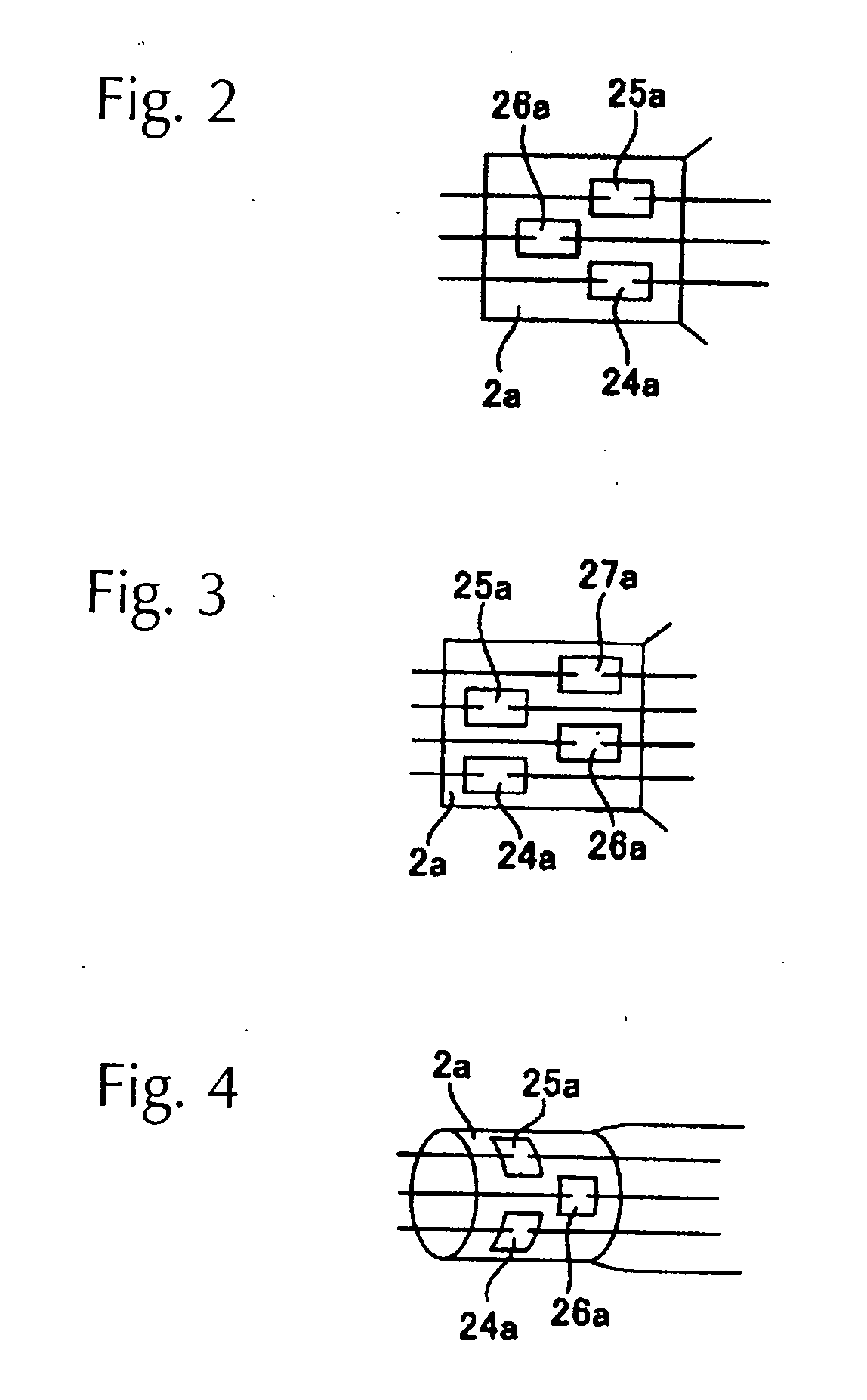
[0025]The present invention is characterized by having a plurality of coil-shaped filaments disposed together in sequence in the tube axis direction of a light-emitting tube respectively in the interior of a light-emitting tube having hermetically sealed parts formed at the ends, with a pair of internal leads connected to the ends of each filament and the internal leads being electrically connected to external leads respectively via a plurality of sheets of metal foil; wherein some of the plurality of sheets of metal foil are disposed in staggered relation to the tube axis direction of the light-emitting tube to form a gap at the edges of the metal foil with respe...


PUM


Abstract

To provide a filament lamp having a plurality of filaments disposed together in sequence in the tube axis direction of a light-emitting tube, with miniaturized hermetically sealed parts, by certain sheets of metal foil (26a, 26b), of the plurality of metal foils (24a, 24b, 25a, 25b, 26a, 26b), being disposed out of alignment with the tube axis direction in relation to the other of the metal foils (24a, 24b, 25a, and 25b), and are also disposed staggered in a direction perpendicular to the tube axis direction.

Description

BACKGROUND OF THE INVENTION[0001]1. Field of Invention[0002]The present invention relates to a filament lamp, and in particular to a filament lamp used to heat an article to be treated.[0003]2. Description of Related Art[0004]Heat treatment devices capable of heating an article to be treated without making contact by optical irradiation from an incandescent lamp or other light source in which filaments are disposed inside a light-emitting tube composed of optically transparent material, for example, are widely used as heat treatment devices in rapid thermal processing (RPT) employed during film formation, oxidation, impurity dispersion, nitriding, film stabilization, silicidation, crystallization, and ion implantation processes that are part of the semiconductor manufacturing process (see, Japanese Unexamined Patent Application JP 7-37833 and Japanese Unexamined Patent Application JP 2002-203804).[0005]In a case in which this kind of optical irradiation type heat treatment device is...

Claims


Application Information

Patent Timeline
IPC IPC(8): H01K9/00
CPCH01K1/38H01K9/08H01K7/00A01K11/006A61D7/00A61M5/178A61M2205/35A61M2205/60A61M2250/00
Inventor NAKASHIMA, AKINOBUTANINO, KENJI
Owner USHIO DENKI KK
Why Eureka
Try Eureka