

Method for activating reactive oxygen species for cleaning carbon-based film deposition
a technology of reactive oxygen species and carbon-based film, which is applied in the direction of plasma technique, coating, chemistry apparatus and processes, etc., can solve the problems of insufficient cleaning at the locations, short oxygen ions, and time-consuming plasma cleaning process known remotely
- Summary
- Abstract
- Description
- Claims
- Application Information
AI Technical Summary
Problems solved by technology
Method used
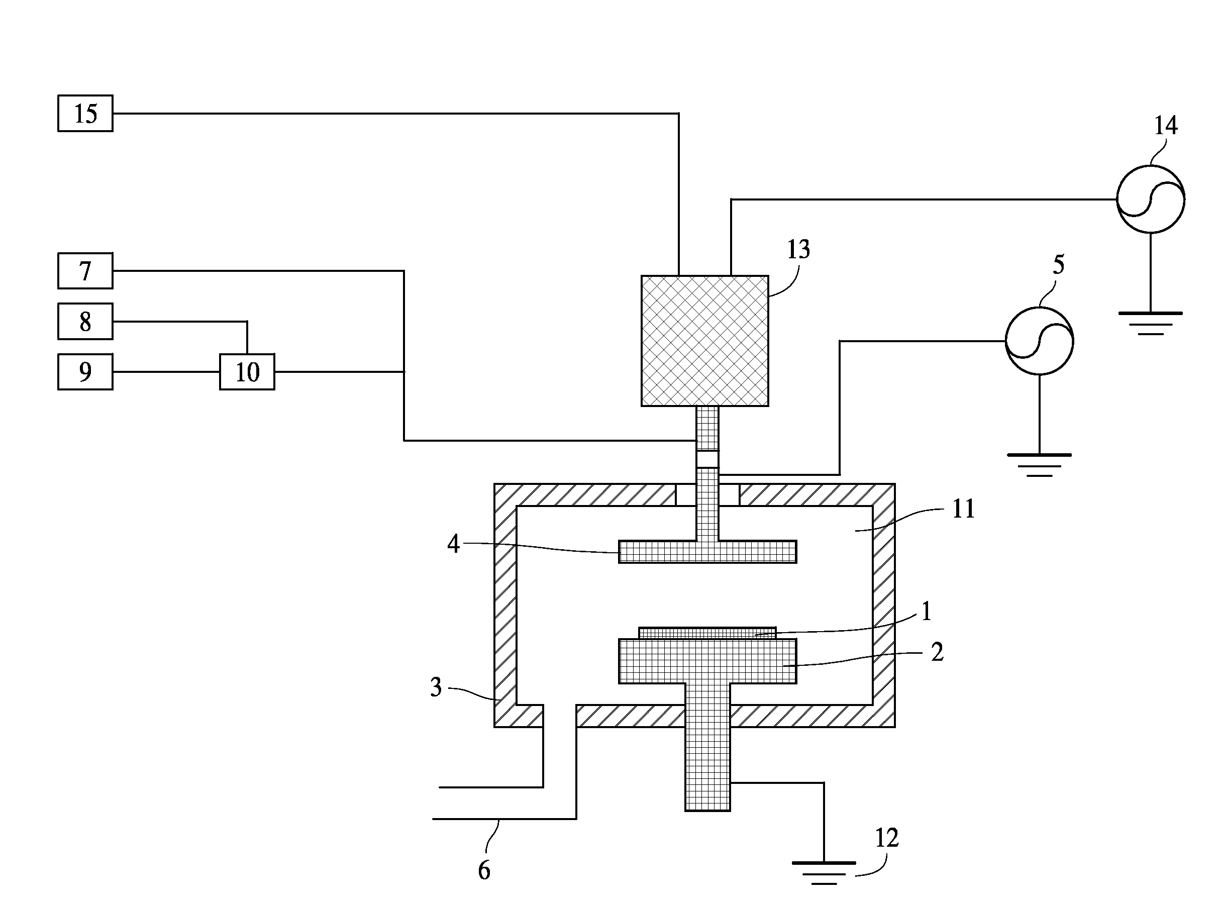
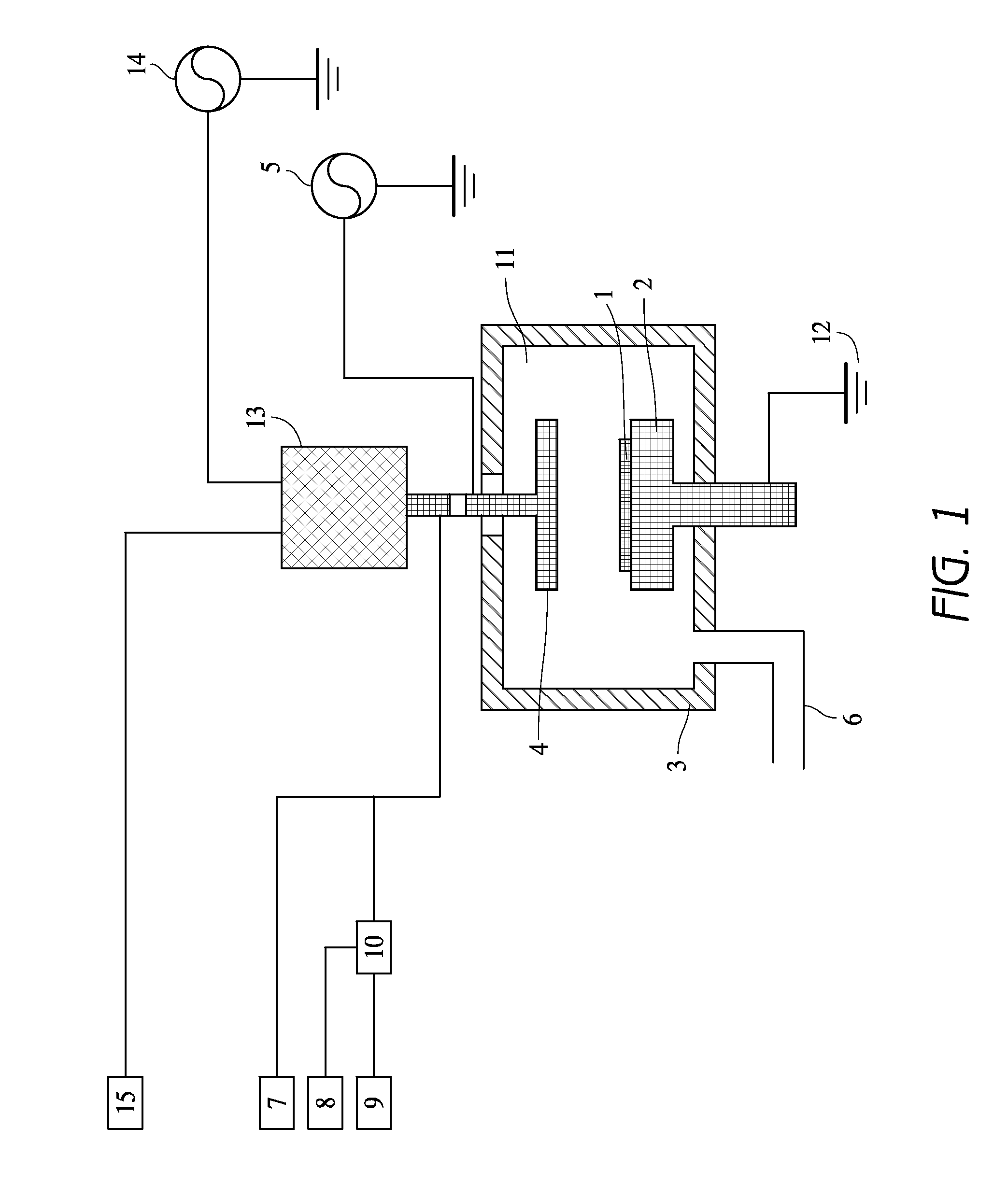
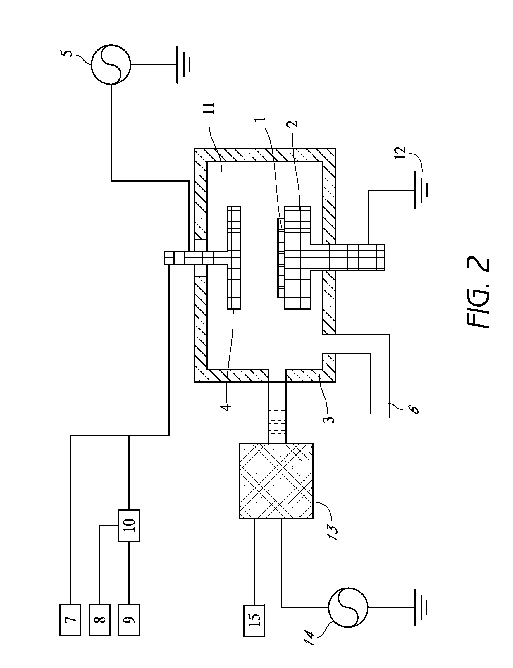
Image

Examples
example 1
[0092]As a cleaning gas, O2 gas was used. Ar gas was used for igniting plasma at the remote plasma unit. It took about 5 sec to ignite plasma. After ignition Ar flow was increased to the set point and supplied to the remote plasma unit. Cleaning conditions in this example and cleaning results are shown as follows. A cleaning rate was evaluated based on an etching rate on the carbon-based polymer film deposited on the substrate. In the examples, the etching rates were treated as cleaning rates.
[0093]Cleaning Conditions:
[0094]Gap between shower plate and susceptor: 25 mm
[0095]Susceptor temperature: 340° C.
[0096]Ar gas supplied to the remote plasma unit: 5,000 sccm
[0097]O2 gas supplied to the remote plasma unit: 1,000, 1,500, 2,000 sccm
[0098]No fluorine-containing gas supplied to the remote plasma unit
[0099]Cleaning time: 20 sec
[0100]Cleaning Rates:
[0101]17.9 nm / min at 1,000 sccm of O2
[0102]22.8 nm / min at 1,500 sccm of O2
[0103]24.0 nm / min at 2,000 sccm of O2
[0104]FIG. 3 shows the re...
example 2
[0105]Under the same conditions as in Example 1 except that nitrogen tri-fluoride gas was continuously supplied to the remote plasma unit at a constant rate after the ignition. A cleaning rate (etching rate) was evaluated in the same way as in Example 1.
[0106]Cleaning Conditions:
[0107]Gap between shower plate and susceptor: 25 mm
[0108]Susceptor temperature: 340° C.
[0109]Ar gas supplied to the remote plasma unit: 5,000 sccm,
[0110]Nitrogen tri-fluoride gas supplied to the remote plasma unit: 100 sccm,
[0111]O2 gas supplied to the remote plasma unit: 1,000 scc, 1,500 sccm, 2,000 sccm
[0112]Cleaning time: 20 sec
[0113]Cleaning Rates:
[0114]325 nm / min at nitrogen tri-fluoride 100 sccm, 1,000 sccm of O2,
[0115]1453 nm / min at nitrogen tri-fluoride 100 sccm, 1,500 sccm of O2
[0116]2172 nm / min at nitrogen tri-fluoride 100 sccm, 2,000 sccm of O2
[0117]FIG. 4 shows the surprising results of adding nitrogen tri-fluoride gas to oxygen gas flow. As compared with Example 1, when nitrogen tri-fluoride w...
example 3
[0118]Under the same conditions as in Example 2 except that the flow rate of nitrogen tri-fluoride gas was changed while the flow rate of O2 and Argon gas was constant. A cleaning rate (etching rate) was evaluated in the same way as in Example 1.
Cleaning Conditions:
[0119]Gap between shower plate and susceptor: 25 mm
[0120]Susceptor temperature: 340° C.
[0121]Ar gas supplied to the remote plasma unit: 5,000,
[0122]O2 gas supplied to the remote plasma unit: 2,000 sccm
[0123]nitrogen tri-fluoride gas supplied to the remote plasma unit: 100 sccm, 200 sccm, 300 sccm, 400 sccm
[0124]Cleaning time: 20 sec
[0125]Cleaning Rates:
[0126]214 nm / min at 400 sccm of nitrogen tri-fluoride
[0127]321 nm / min at 300 sccm of nitrogen tri-fluoride
[0128]1278 nm / min at 200 sccm of nitrogen tri-fluoride
[0129]2172 nm / min at 100 sccm of nitrogen tri-fluoride
[0130]FIG. 5 shows the results of the gas ratio of nitrogen tri-fluoride gas to the total gas flow (nitrogen tri-fluoride, argon, oxygen). As for the ratio of nit...
PUM
| Property | Measurement | Unit |
|---|---|---|
| temperature | aaaaa | aaaaa |
| pressure | aaaaa | aaaaa |
| boiling point | aaaaa | aaaaa |
Abstract
Description
Claims
Application Information