Membrane electrode assembly and fuel cell

a membrane electrode and fuel cell technology, applied in the field of fuel cells, can solve the problems of short circuit, electrolyte membrane deterioration, hydrogen leakage, etc., and achieve the effect of narrowing the interval (spacing), preventing short circuit, and narrowing the interval

Inactive Publication Date: 2009-10-01
SANYO ELECTRIC CO LTD
View PDF2 Cites 31 Cited by
  • Summary
  • Abstract
  • Description
  • Claims
  • Application Information

AI Technical Summary

Benefits of technology

[0009]The present invention has been made in view of the foregoing problems, and an advantage thereof is to provide a technology capable of narrowing the interval (spacing) between cells while short-circuiting is prevented in a planar fuel cell with its cells disposed in a planar arrangement. Another advantage thereof is to provide a technology capable of narrowing the interval (spacing) between cells while a damage to the electrolyte membrane is prevented in a planar fuel cell with its cells disposed in a planar arrangement.

Problems solved by technology

Serious technical efforts are being made to develop practical fuel cells.
However, as the spacing between the catalyst layers gets smaller and shorter, a problem of short-circuiting arises.
In the forming of catalyst layers disposed at fine intervals, laser processing is useful but there is a problem where the laser processing cuts off the bonding of side chains in a molecular structure of electrolyte membrane.
Also, as the heat caused by the laser processing transfers across the electrolyte membrane, there is another problem where the electrolyte membrane deteriorates.
When such a structural alteration and deterioration occur in the electrolyte membrane and also hydrogen is used as fuel, a problem arises where the hydrogen leaks and the performance of fuel cell deteriorates.

Method used


Image

  • Membrane electrode assembly and fuel cell
  • Membrane electrode assembly and fuel cell
  • Membrane electrode assembly and fuel cell

Examples


first embodiment

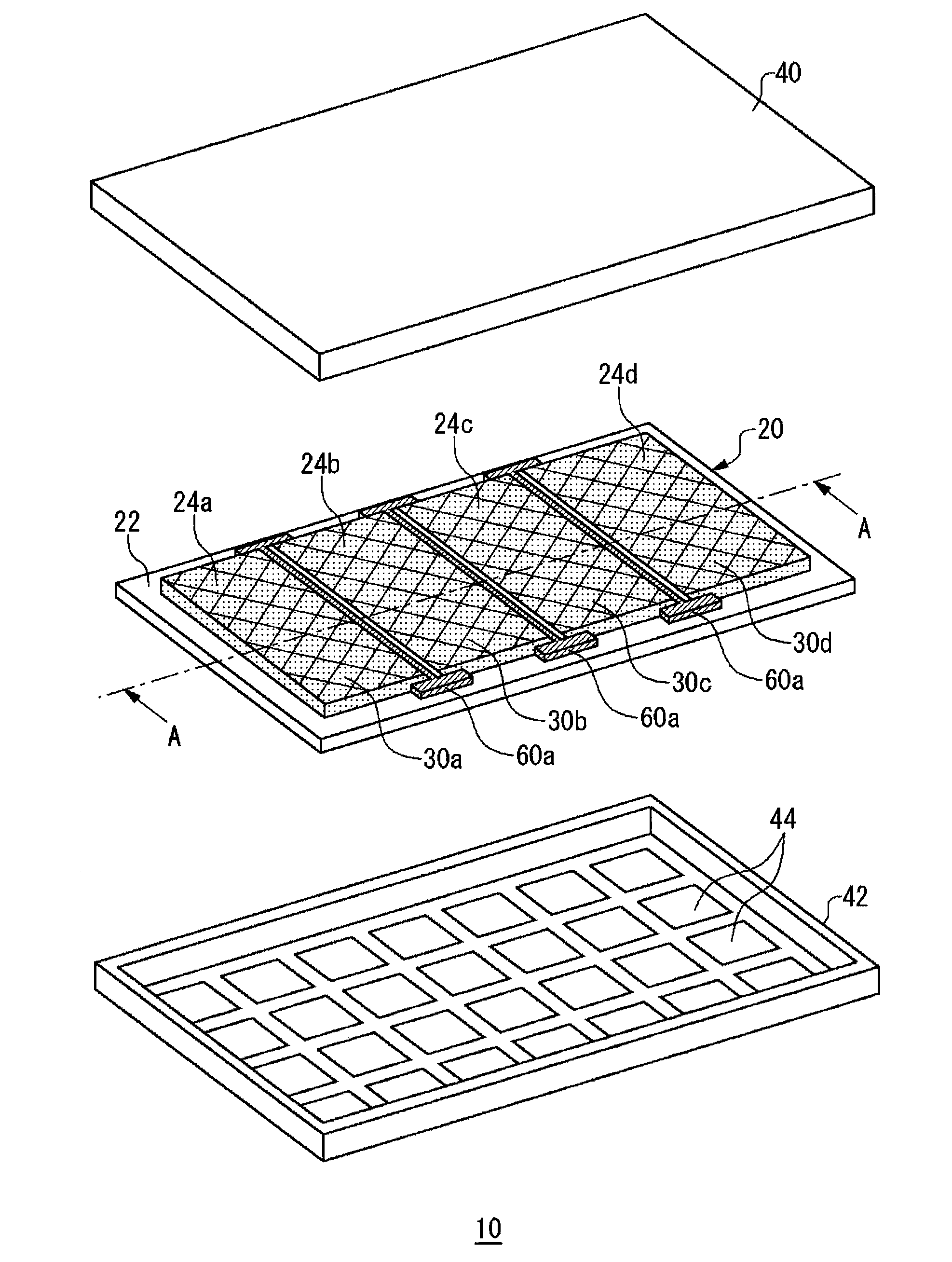
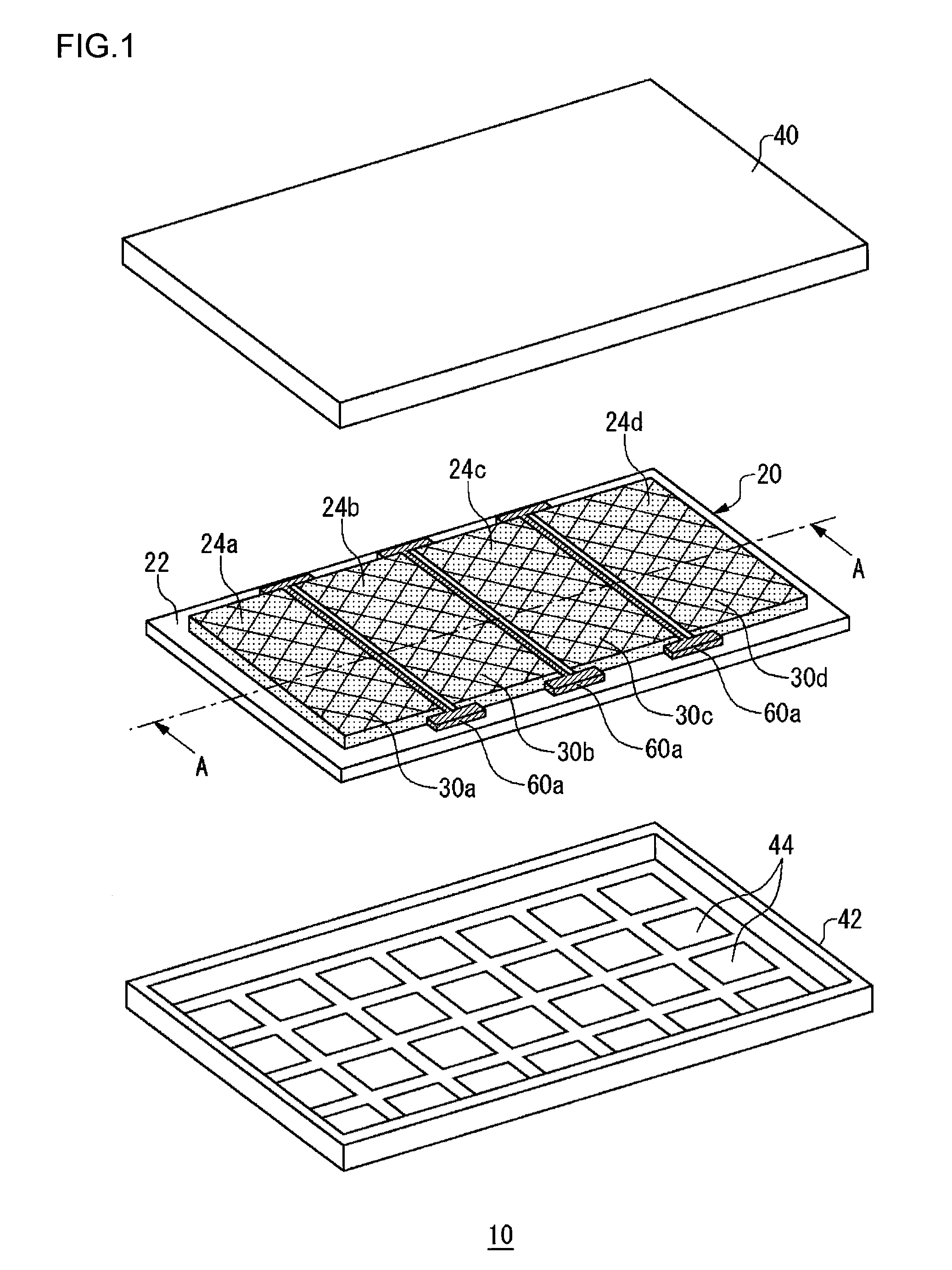
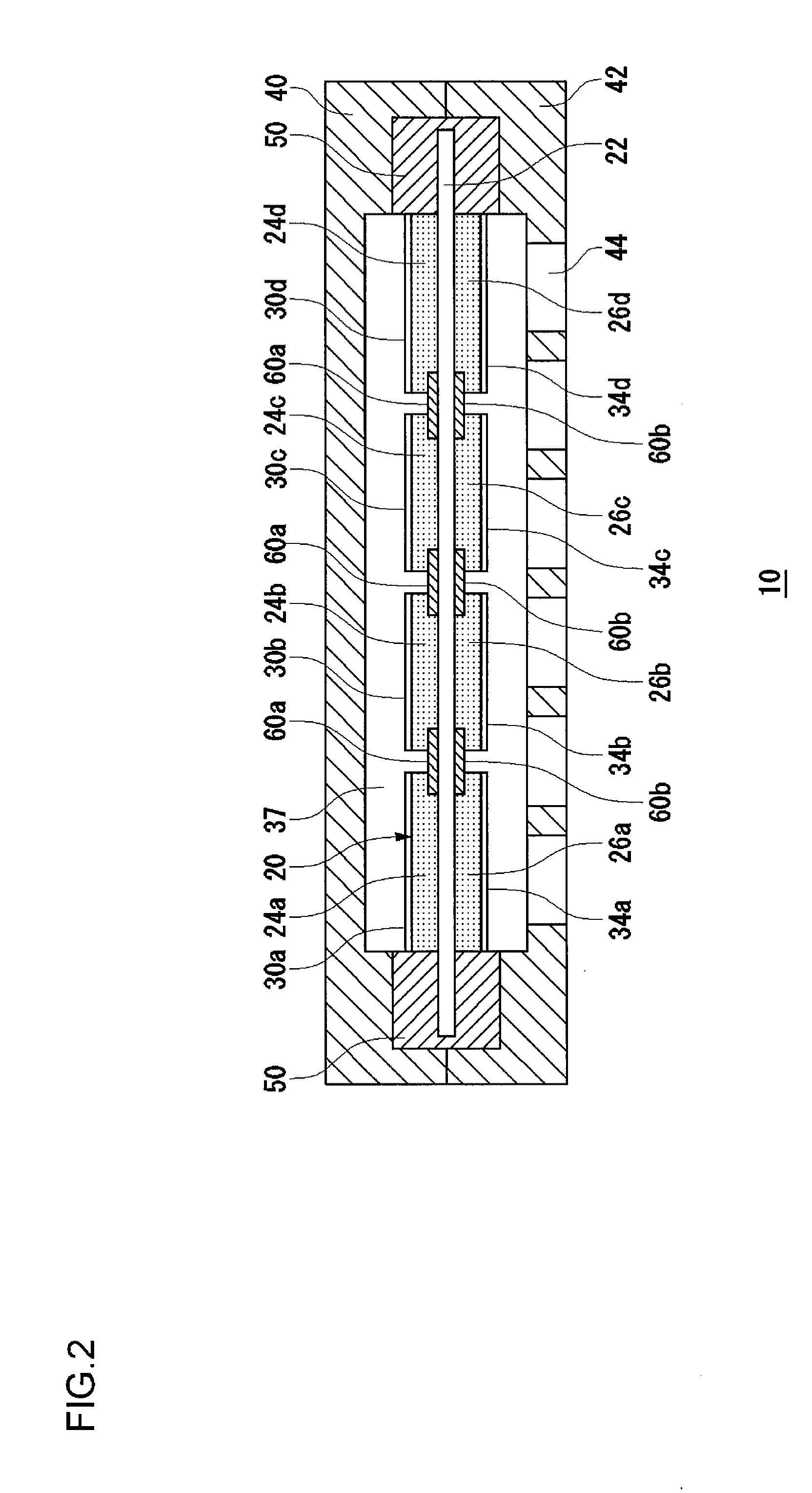
[0032]FIG. 1 is an exploded perspective view showing a structure of a fuel cell according to a first embodiment of the present invention. FIG. 2 is a cross-sectional view taken along the line A-A of FIG. 1. As shown in FIG. 1 and FIG. 2, a fuel cell 10 includes a membrane electrode assembly (MEA, also called a catalyst-coated membrane (CCM)) 20, an anode housing 40, and a cathode housing 42. A sealing member 50 (described later) is provided around the peripheral edge part of the membrane electrode assembly 20.

[0033]The membrane electrode assembly 20 includes an electrolyte membrane 22, anode catalyst layers 24a to 24d, and cathode catalyst layers 26a to 26d, which are disposed counter to the anodes 24a to 24d, respectively. Hereinafter, the anode catalyst layers 24a to 24d may be collectively called “anode catalyst layer 24” also, and the cathode catalyst layers 26a to 26d may be collectively called “cathode catalyst layer 26” also. Hydrogen is supplied to the anode catalyst layers ...

example 1

[0070]In Example 1, Nafion membrane is used as the electrolyte membrane. The Nafion membrane is formed on the electrolyte membrane as an insulating layer. The catalyst slurry by using Nafion as an ionomer is applied to both faces of the electrolyte membrane so as to prepare a membrane electrode assembly of Example 1. That is, in the membrane electrode assembly according to the first embodiment, the same material is used for both the electrolyte membrane and the insulating layer. Then the laser processing is performed on only one surface of the membrane electrode assembly by using excimer laser.

example 2

[0074]In Example 2, Nafion membrane is used as the electrolyte membrane. The Nafion membrane is formed on the electrolyte membrane as an insulating layer. Then the catalyst slurry using sulfonated polystyrene-block-poly(ethylene-ran-butylene)-block-polystyrene as an ionomer is applied to both faces of the electrolyte membrane so as to prepare a membrane electrode assembly of Example 2. The laser processing is performed on only one surface of the membrane electrode assembly by using excimer laser.

Experimental Result 2

[0075]An observation of Comparative Example 1, which is a photograph of a membrane electrode assembly, after subjected to laser irradiation, according to Comparative Example 1 is shown in FIG. 5. Bubble-like matters occur in regions which are irradiated with laser. This verifies that the electrolyte membrane is damaged by laser irradiation.

[0076]An observation of Example 1, which is a photograph of a membrane electrode assembly, after subjected to laser irradiation, acco...


PUM

PropertyMeasurementUnit
widthaaaaaaaaaa
thicknessaaaaaaaaaa
widthaaaaaaaaaa

Abstract

A membrane electrode assembly includes an electrolyte membrane, anode catalyst layers, and cathode catalyst layers provided counter to the anode catalyst layers, respectively. An insulating layer is provided on the electrolyte membrane between adjacent anode catalyst layers. An insulating layer is provided on the electrolyte membrane between adjacent cathode catalyst layers. The resistivity of the insulating layer is preferably identical to or higher than that of the electrolyte membrane.

Description

CROSS-REFERENCE TO RELATED APPLICATIONS[0001]This application is based upon and claims the benefit of priority from the prior Japanese Patent Applications No. 2008-091635, filed Mar. 31, 2008, and Japanese Patent Application No. 2009-019120, filed Jan. 30, 2009, the entire contents of which are incorporated herein by reference.BACKGROUND OF THE INVENTION[0002]1. Field of the Invention[0003]The present invention relates to a fuel cell and, in particular, to a fuel cell with its cells disposed in a planar arrangement.[0004]2. Description of the Related Art[0005]A fuel cell is a device that generates electricity from hydrogen and oxygen so as to obtain highly efficient power generation. A principal feature of a fuel cell is its capacity for direct power generation which does not undergo a stage of thermal energy or kinetic energy as in conventional power generation. This presents such advantages as high power generation efficiency despite the small scale setup, reduced emission of nitr...

Claims


Application Information

Patent Timeline
Patent Type & Authority Applications(United States)
IPC IPC(8): H01M8/10
CPCH01M4/881H01M4/8817H01M4/8828H01M8/1004H01M8/1023H01M8/1027H01M4/8647H01M8/1039H01M8/1053H01M8/1067H01M8/241Y02E60/521H01M8/103H01M8/242Y02E60/50
Inventor NOWATARI, YUKOISONO, TAKAHIRO
Owner SANYO ELECTRIC CO LTD
Why Eureka
Try Eureka