Method for controlling flow of urine in a patient's urethra, ureter, renal pelvis or bladder

a technology for urethra, ureter, renal pelvis or urine bladder, applied in the direction of prosthesis, artificial respiration, therapy, etc., can solve the problems of severe urine leakage, inability to pump, and inability to control the flow of urin

Active Publication Date: 2009-10-01
FORSELL PETER
View PDF25 Cites 87 Cited by
  • Summary
  • Abstract
  • Description
  • Claims
  • Application Information

AI Technical Summary

Benefits of technology

[0022]a) gently constricting a portion of the tissue wall of the urethra, ureter, renal pelvis or bladder to influence the flow in the urinary passageway, and
[0023]b) stimulating the constricted wall portion to cause contraction of the wall portion to further influence the flow in the urinary passageway.
[0024]The present invention provides an advantageous combination of the method steps (a) and (b), which results in a two-stage influence on the flow of urine in the urinary passageway of a patient's urethra, ureter, renal pelvis or bladder. Thus, applying a relatively weak force against the wall portion gently constricts the tissue wall and the constricted wall portion is stimulated to achieve the desired final influence on the flow in the urinary passageway. The phrase “gently constricts a portion of the tissue wall” is to be understood as constricting the wall portion without substantially hampering the blood circulation in the tissue wall.

Problems solved by technology

In a urinary stress incontinent patient the urethral sphincter is unable to prevent urine from being expelled from the bladder during transient increase in intra-abdominal pressure, which can be caused by sneezing, coughing or laughing, or by lifting heavy goods.
Although some people suffering from these diseases are helped through training of the muscles in the pelvic floor, too many have severe problems with urine leakage.
A disadvantage of this prior apparatus is that over time hard fibrosis is developed around the reservoir, which may cause malfunction of pumping components.
Furthermore, it is a rather complicated task to manually squeeze the elastic implanted reservoir to pump hydraulic fluid to open the sphincter device when the patient needs to urinate.
The created fibrosis will sooner or later become a hard fibrotic layer, which may make it even more difficult to pump the reservoir.
Yet a further disadvantage is that the use of hydraulic fluid always entails a risk of fluid leaking from implanted hydraulic components.
A disadvantage common to all prior artificial sphinters is that hard fibrosis may form around the artificial sphincter over time and may cause malfunction of the artificial sphincter.
Thus, the formed fibrosis may sooner or later become a hard fibrotic layer which may make it difficult for the artificial sphincter to work.
Another more serious disadvantage of the prior artificial sphincters if used for replacing malfunctioning urethral sphincters is that the element that constricts, clamps or restricts the urethra may injure the tissue wall of the urethra.
Thus, a consequence of the element's constricting action on the urethra is that the element might erode into the urethra over time, and in a worst case, penetrate the constricted wall portion of the urethra.
In addition, blood circulation in the constricted tissue wall portion of the urethra is eventually hampered by the pressure exerted by the element, so that poor blood circulation, or worse, no blood circulation results in deterioration of the constricted tissue.
First, the apparatus would require a large amount of space, making it impractical to implant.
Second, the operation of the apparatus in moving the constricting elements between constricting and non-constricting positions day and night would require a large power supply.
Thus, because of its large size and high power consumption, the apparatus would be impractical or even unrealistic.
Finally, such a complicated apparatus of the type described above would significantly add to the costs of treating a malfunctioning sphincter.
However, the esophageal sphincter has to be continuously stimulated with electric pulses to keep it closed, except when the patient eats, which may result in a decreased stimulation effect over time.
An even more serious drawback to this solution is that the continuous stimulation over time might cause tissue deterioration due to poor blood circulation.
In cases where the sphincteric function of a urethral sphincter has completely ceased, or the urethral sphincter has been removed from the patient's body, electric stimulation cannot be employed.
For example, it is true that electric stimulation of the urethra affects flow of urine, but could not possibly fully close the relatively stiff urethra, at least not by employing the necessary low stimulation intensities that are harmless to the human body.

Method used


Image

  • Method for controlling flow of urine in a patient's urethra, ureter, renal pelvis or bladder
  • Method for controlling flow of urine in a patient's urethra, ureter, renal pelvis or bladder
  • Method for controlling flow of urine in a patient's urethra, ureter, renal pelvis or bladder

Examples


Embodiment Construction

See Below

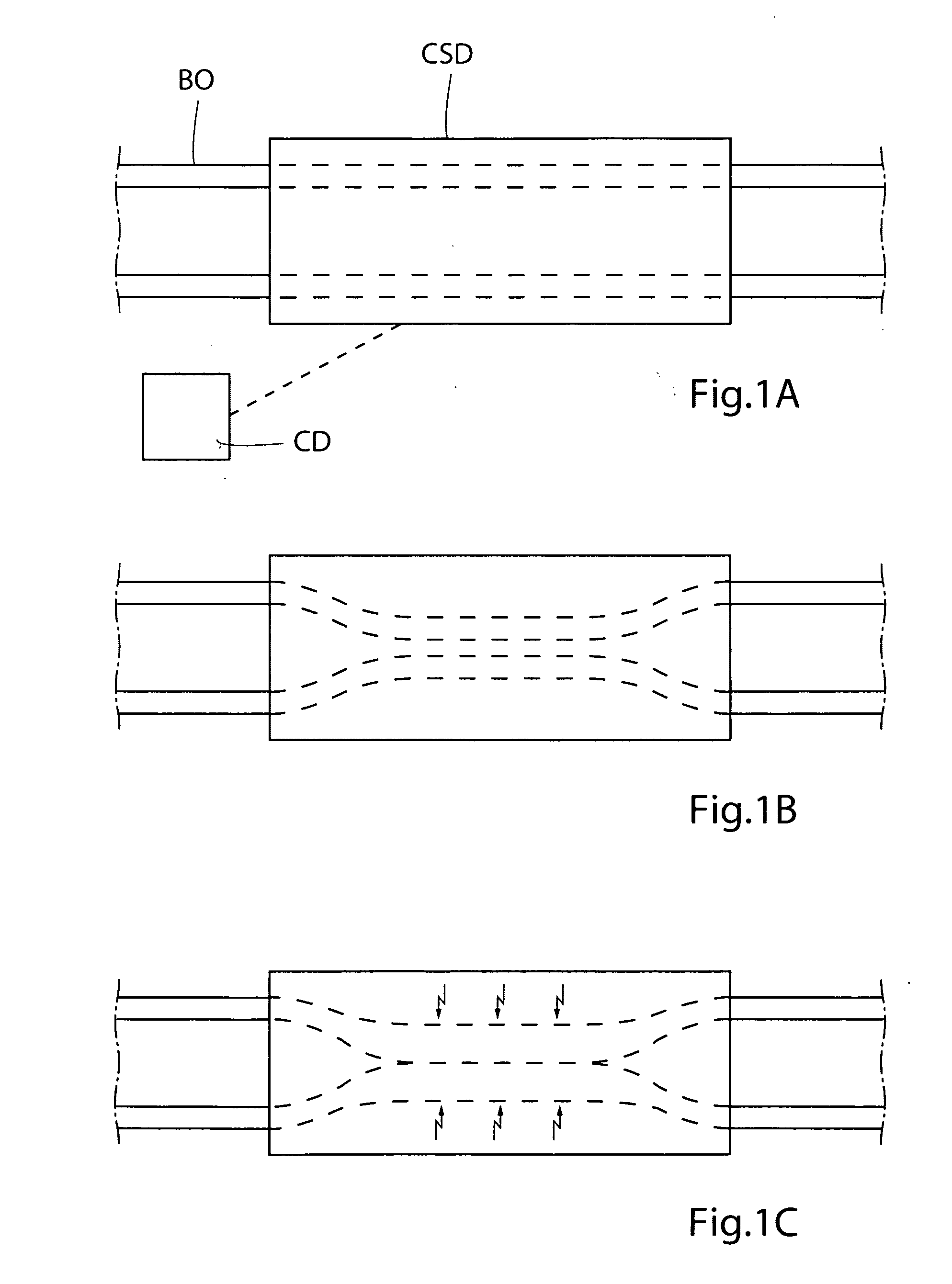
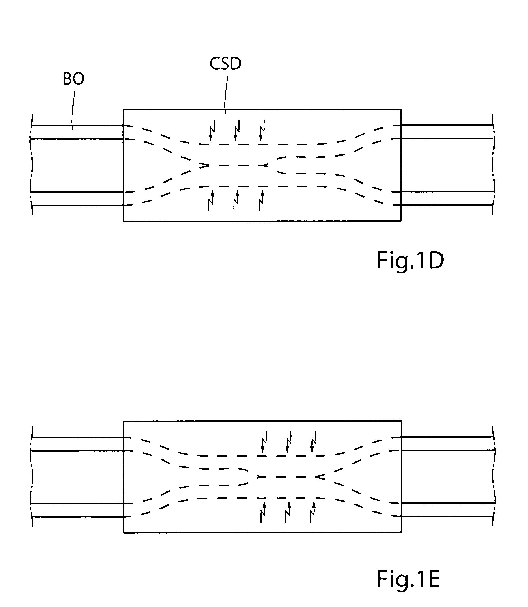
[0060]In accordance with an alternative, step (a) is performed by constricting any wall portions of a series of wall portions of the tissue wall of the urethra, ureter, renal pelvis or bladder, respectively. In accordance with an alternative, the wall portions of the series of wall portions are constricted in random or in accordance with a predetermined sequence. In accordance with an alternative, the wall portions of the series of wall portions are successively constricted along the urethra, ureter, renal pelvis or bladder to move the urine in the urinary passageway of the patient's urethra, ureter, renal pelvis or bladder or to prevent the urine to move in the lumen of the patient's urethra, ureter, renal pelvis or bladder.

[0061]In accordance with an alternative, step (b) is performed by stimulating any constricted wall portions of the series of wall portions. In accordance with an alternative, the wall portions of the series of wall portions are constricted in random or ...


PUM


Abstract

There is provided a method for controlling a flow of urine in the urinary passageway of a patient's urethra, ureter, renal pelvis or bladder. The method comprises gently constricting (i.e., without substantially hampering the blood circulation in the urinary tissue wall) at least one portion of the urinary tissue wall to influence the flow in the urinary passageway, and stimulating the constricted wall portion to cause contraction of the wall portion to further influence the flow in the urinary passageway. The method can be used for restricting or stopping the flow in the urinary passageway of a urinary incontinent patient, or for actively moving the urine in the urinary passageway, with a low risk of injuring the urethra, ureter, renal pelvis or bladder.

Description

CROSS-REFERENCE TO RELATED APPLICATION[0001]This application claims the benefit of Provisional Application No. 60 / 960,716, filed Oct. 11, 2007, the entire contents of which are hereby incorporated by reference in this application.FIELD OF THE INVENTION[0002]The present invention relates to controlling the flow of urine in the urethra, ureter, renal pelvis or urine bladder, and in particular, to a method for controlling the flow of flow urine of a patient suffering from urinary dysfunctionurineurineurethra, ureter, renal pelvis or bladder.BACKGROUND OF THE INVENTION[0003]There are different kinds of urinary dysfunction that prevent a patient from maintaining normal control of the flow of urine in the patient's urethra, ureter, renal pelvis or bladder. For example, overflow incontinence, stress incontinence and urge incontinence. (The term “patient” generally includes human beings, but may also include animals.)[0004]Overflow incontinence involves disability of controlling the muscle ...

Claims


Application Information

Patent Timeline
Patent Type & Authority Applications(United States)
IPC IPC(8): A61F2/02A61N1/36
CPCA61M1/1068A61N1/3605A61N1/36514A61M1/122A61N1/36578A61N1/403A61N1/36564A61F2/0036A61F2/004A61F2250/0013A61M2205/33A61M2205/3303A61M2205/8243A61M60/148
Inventor FORSELL, PETER
Owner FORSELL PETER
Why Eureka
Try Eureka