Diesel Turbine SCR Catalyst

Active Publication Date: 2009-10-08
FORD GLOBAL TECH LLC
View PDF12 Cites 12 Cited by
  • Summary
  • Abstract
  • Description
  • Claims
  • Application Information

AI Technical Summary

Benefits of technology

[0005]In this way, by first combining and then separating the exhaust gases ejected by the engine prior to injecting a liquid reductant and passing the re-combined exhaust gas flow through the turbocharger, the exhaust treatment system may be more compactly and flexibly packaged and may thus allow for more flexibility in the arrangement and packaging of other vital vehicle components. Correspondingly, the ease and cost of manufacturing such an exhaust treatment system may be reduced. Furthermore, by first combining the exhaust gases ejected by individual cylinders, separating the resulting single exhaust gas flow and then re-combining the exhaust gas flow into a re-combined exhaust gas flow, the geometrical relationship between the plurality of separated exhaust gas flows upon being re-combined by the second downstream flow combining passage may be configured such that a more turbulent re-combined flow may be realized. This increased turbulence within the re-combined flow may increase the breakdown (into ammonia) and distribution of a liquid reductant (within the re-combined exhaust gas flow) injected therein.
[0006]By arranging oxidation catalysts u

Problems solved by technology

In particular, because the exhaust gases are delivered separately from the cylinders to the upstream catalyst 5, the packaging of multiple oxidation catalysts within individual exhaust manifold tubes may increase packaging constrai

Method used


Image

  • Diesel Turbine SCR Catalyst
  • Diesel Turbine SCR Catalyst
  • Diesel Turbine SCR Catalyst

Examples


Embodiment Construction

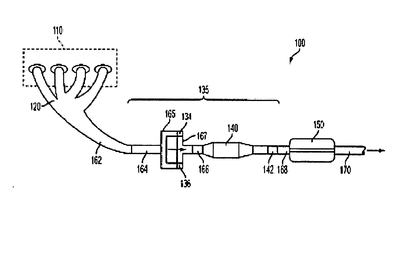
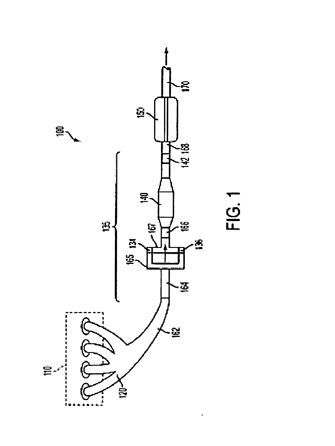
[0011]FIG. 1 illustrates an exhaust system 100 for transporting and treating exhaust gases produced by internal combustion engine 110. As one non-limiting example, engine 110 includes a diesel engine that produces a mechanical output by combusting a mixture of air and diesel fuel. Alternatively, engine 110 may include other types of engines such as gasoline burning engines, among others. Further, engine 110 may be configured in a propulsion system for a vehicle. Alternatively, engine 110 may be operated in a stationary application, for example, as an electric generator. While exhaust system 100 may be applicable to stationary applications, it should be appreciated that exhaust system 100 as described herein, is particularly adapted for vehicle applications.

[0012]Exhaust system 100 may include one or more of the following: an exhaust manifold 120 for receiving exhaust gases produced by one or more cylinders of engine 110, oxidation catalysts 134 and 136 arranged downstream of exhaust...


PUM


Abstract

A system for treating exhaust gases from an engine is described. The system includes, the exhaust gases routed from the engine to atmosphere through an exhaust passage, the system comprising: an injector directing a spray of reductant into the exhaust gases routed from the engine to atmosphere; an exhaust separation passage that separates an exhaust gas flow received from the engine into a plurality of separate exhaust gas flows; a plurality of oxidation catalysts, each of which receives one of the plurality of separate exhaust gas flows; a flow combining passage that receives the plurality of separate exhaust gas flows and combines them into a re-combined exhaust gas flow; a turbocharger that receives the re-combined exhaust gas flow from the flow combining passage; and a selective catalytic reduction catalyst positioned downstream of the turbocharger.

Description

BACKGROUND AND SUMMARY [0001]An engine exhaust system may include various components to enhance engine operation and reduce emissions. These may include selective catalytic reduction (SCR) catalysts, oxidation catalysts, NOx traps, turbochargers, exhaust gas recirculation, etc.[0002]One example of such an engine exhaust system is described in U.S. 2006 / 0080953. In the exhaust system described in U.S. 2006 / 0080953, a reducing agent is supplied to an exhaust gas stream upstream of a turbocharger that aids in the breakdown and distribution of the reducing agent (suspended within the exhaust gas stream) prior to the exhaust gas stream reaching a downstream oxidation and SCR catalyst. Furthermore, in this example, multiple separate exhaust gas flows from multiple cylinders are funneled through individual oxidation catalysts, each of the individual oxidation catalysts arranged in an individual tube of an exhaust manifold. Thus, as described in U.S. 2006 / 0080953, separate exhaust flows are...

Claims


Application Information

Patent Timeline
IPC IPC(8): F01N3/10
CPCF01N3/103F01N3/2066F01N2240/20F01N2240/40F01N13/017F01N2610/02F02B37/00Y02T10/144Y02T10/24F01N2510/06Y02T10/12
Inventor LAMBERT, CHRISTINE KAYHUANG, YINYANSUN, HAROLD HUIMINOBERSKI, CHRISTOPHER
Owner FORD GLOBAL TECH LLC
Why Eureka
Try Eureka