Extreme ultra violet light source apparatus

a light source and ultra violet technology, applied in the field of extreme ultra violet (euv) light source apparatus, can solve the problems of reducing the performance of the euv light source apparatus, so as to prevent the attachment, reduce the reflectance or transmittance of the optical elements, and prevent the movement of debris within the chamber

Active Publication Date: 2009-10-08
GIGAPHOTON
View PDF6 Cites 33 Cited by
  • Summary
  • Abstract
  • Description
  • Claims
  • Application Information

AI Technical Summary

Benefits of technology

[0017]According to the one aspect of the present invention, the gas is supplied into the chamber of the ultra violet light source apparatus and excited to generate the second plasma around the region where the first plasma, and the debris emitted from the first plasma are gasified and ejected to the outside of the chamber, and therefore, the debris are prevented from attaching to the optical elements within the chamber. Thereby, the debris moving within the chamber are prevented from reducing reflectance or transmittance of the optical elements of the EUV collector mirror and so on, and extreme ultra violet light can stably be generated in a long period.

Problems solved by technology

However, part of the generated positive ions recombine with electrons and become neutral particles, move without being constrained by the magnetic field, and attach to the surfaces of the optical elements within the chamber to reduce the reflectance and transmittance of EUV light, and thereby, reduce the performance of the EUV light source apparatus.
Especially, polyvalent positive ions of tin or the like easily recombine with electrons and reduce the performance of the EUV light source apparatus.
Further, it is difficult to ionize all target materials by the excitation laser, and part of the target materials become neutral debris, move without being constrained by the magnetic field, and attach to the optical elements within the chamber to reduce the reflectance or transmittance of EUV light, and thereby, reduce the performance of the EUV light source apparatus.

Method used


Image

  • Extreme ultra violet light source apparatus
  • Extreme ultra violet light source apparatus
  • Extreme ultra violet light source apparatus

Examples


first embodiment

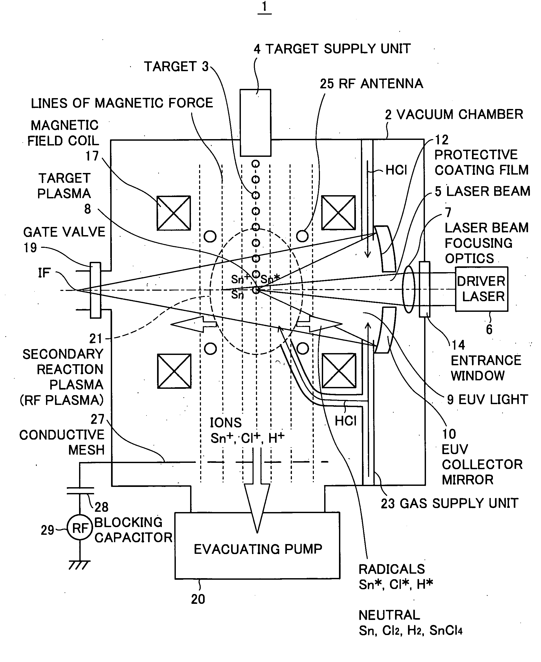
[0024]FIG. 1 is a schematic diagram showing an extreme ultra violet (EUV) light source apparatus according to the present invention. The EUV light source apparatus employs a laser produced plasma (LPP) type and is used as a light source of exposure equipment.

[0025]As shown in FIG. 1, the EUV light source apparatus 1 includes a vacuum chamber 2 in which EUV light is generated, a target supply unit 4 for supplying a target 3 to a predetermined position within the vacuum chamber 2, a driver laser 6 for generating an excitation laser beam 5 to be applied to the target 3, a laser beam focusing optics 7 for focusing the excitation laser beam 5 generated by the driver laser 6, an EUV collector mirror 10 for collecting and outputting EUV light 9 emitted from plasma 8 (hereinafter, also referred to as “target plasma”) generated when the excitation laser beam 5 is applied to the target 3, a magnetic field generating unit including a magnetic field coil 17 for generating a magnetic field that ...

second embodiment

[0040]Next, the present invention will be explained.

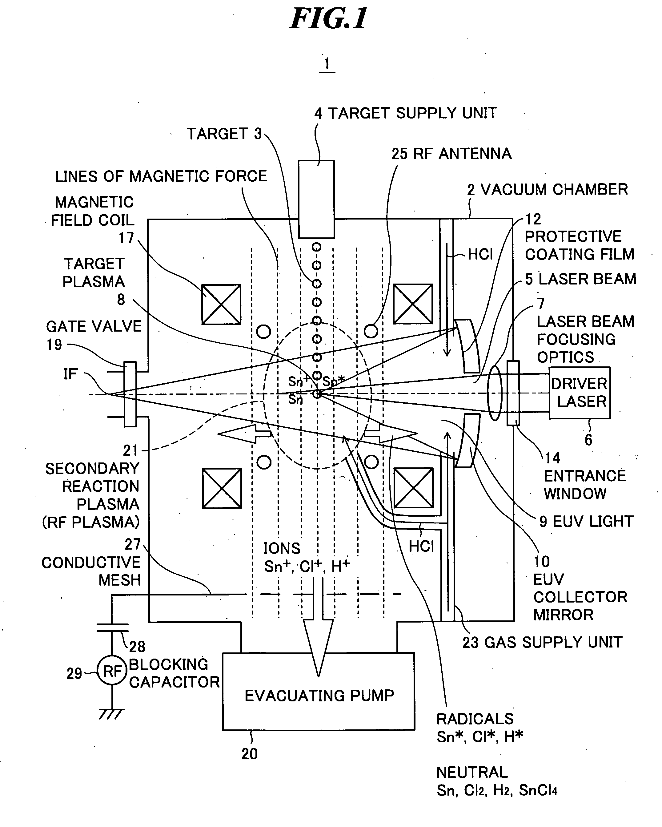
[0041]FIG. 2 shows an internal structure of an EUV light source apparatus according to the second embodiment of the present invention. As shown in FIG. 2, the EUV light source apparatus 31 includes the same configuration as that of the EUV light source apparatus according to the first embodiment, however, excites a secondary reaction plasma 32 by using a magnetic field and microwaves in place of the radio-frequency electric field. The magnetic field is generated by the magnetic field coil 17, for example, and the microwaves are generated by a microwave generating unit (excitation unit) 35 for exciting a gas by generating microwaves.

[0042]Here, the case of using hydrogen bromide gas (HBr) as the secondary reaction plasma 32 will be explained as an example. By the influence of the magnetic field and the microwaves, the electrons in the hydrogen bromide gas molecules are accelerated by cyclotron resonance, the accelerated electrons co...

third embodiment

[0043]Next, the present invention will be explained.

[0044]FIG. 3 shows an internal structure of an EUV light source apparatus according to the third embodiment of the present invention. As shown in FIG. 3, the EUV light source apparatus 41 includes a target supply unit 44 that can liquefy (or freeze and solidify) tin hydride (SnH4) or halogenated tin (SnCl4, SnBr4) as disclosed in JP-P2006-210157A, for example. Further, the EUV light source apparatus shown in FIG. 3 may include a replenishment gas supply unit 46.

[0045]As below, the case where the target supply unit 44 supplies the liquefied (or frozen and solidified) tin chloride (SnCl4) as a target will be explained as an example. The liquefied (or frozen and solidified) tin chloride (SnCl4) supplied from the target supply unit 44 is excited by the excitation laser beam 5, and thereby, the target plasma 8 for generation of EUV light and the secondary reaction plasma 21 are generated at the same time.

[0046]However, in practice, only...


PUM


Abstract

An extreme ultra violet light source apparatus in which debris moving within a chamber are prevented from reducing reflectance or transmittance of optical elements of an EUV collector mirror, etc, and extreme ultra violet light can stably be generated in a long period. The apparatus includes: a target supply unit for supplying a target to a predetermined position within a chamber; a driver laser for applying a laser beam to the target to generate first plasma; a collector mirror provided within the chamber, for collecting extreme ultra violet light radiated from the first plasma; a gas supply unit for supplying a gas into the chamber; an excitation unit for exciting the gas to generate second plasma around a region where the first plasma is generated; and an exhaust unit for exhausting the chamber and ejecting debris emitted from the first plasma to outside of the chamber.

Description

BACKGROUND OF THE INVENTION[0001]1. Field of the Invention[0002]The present invention relates to an extreme ultra violet (EUV) light source apparatus to be used as a light source of exposure equipment.[0003]2. Description of a Related Art[0004]Recent years, as semiconductor processes become finer, photolithography has been making rapid progress to finer fabrication. In the next generation, microfabrication of 100 nm to 70 nm, further, microfabrication of 50 nm or less will be required. Accordingly, in order to fulfill the requirement for microfabrication of 50 nm or less, for example, exposure equipment is expected to be developed by combining an EUV light source generating EUV light having a wavelength of about 13 nm and reduced projection reflective optics.[0005]As the EUV light source, there are three kinds of light sources, which include an LPP (laser produced plasma) light source using plasma generated by applying a laser beam to a target (hereinafter, also referred to as “LPP ...

Claims


Application Information

Patent Timeline
Patent Type & Authority Applications(United States)
IPC IPC(8): G01J3/10
CPCG03F7/70033G03F7/70916H05G2/005H05G2/008H05G2/003
Inventor MORIYA, MASATOKOMORI, HIROSHIASAYAMA, TAKESHI
Owner GIGAPHOTON
Why Eureka
Try Eureka