Electric motor drive employing hybrid, hysteretic/pulse-width-modulated dynamic braking

a technology of dynamic braking and electric motor, applied in the direction of motor/generator/converter stopper, dynamo-electric converter control, dc motor stopper, etc., can solve the problem of far less ripple voltage during hysteretic control than that obtained with pure hysteretic, and achieve the effect of increasing the power handling capacity of solid-state switching device, reducing switching frequency, and small increase in bus voltage rippl

Active Publication Date: 2009-10-08
ROCKWELL AUTOMATION TECH
View PDF4 Cites 16 Cited by
  • Summary
  • Abstract
  • Description
  • Claims
  • Application Information

AI Technical Summary

Benefits of technology

[0011]The present inventors have recognized that the advantages of PWM control can be obtained without the need to de-rate the solid-state switching device by employing a hybrid control strategy that uses PWM control up to a certain DC bus voltage and then switching to hysteretic control. By moving to hysteretic control, the power handling capacity of the solid-state switching device is effectively increased at the point where greatest power handling is required. Further, because the hysteresis takes place only at high DC bus voltages (essentially switching between two high voltage values) the amount of ripple voltage during the hysteretic control is far less than that obtained with a pure hysteretic control system. Switching to hysteretic control via pulse dropping lowers the switching frequency with only a small increase in bus voltage ripple.

Problems solved by technology

Further, because the hysteresis takes place only at high DC bus voltages (essentially switching between two high voltage values) the amount of ripple voltage during the hysteretic control is far less than that obtained with a pure hysteretic control system.

Method used


Image

  • Electric motor drive employing hybrid, hysteretic/pulse-width-modulated dynamic braking
  • Electric motor drive employing hybrid, hysteretic/pulse-width-modulated dynamic braking
  • Electric motor drive employing hybrid, hysteretic/pulse-width-modulated dynamic braking

Examples


Embodiment Construction

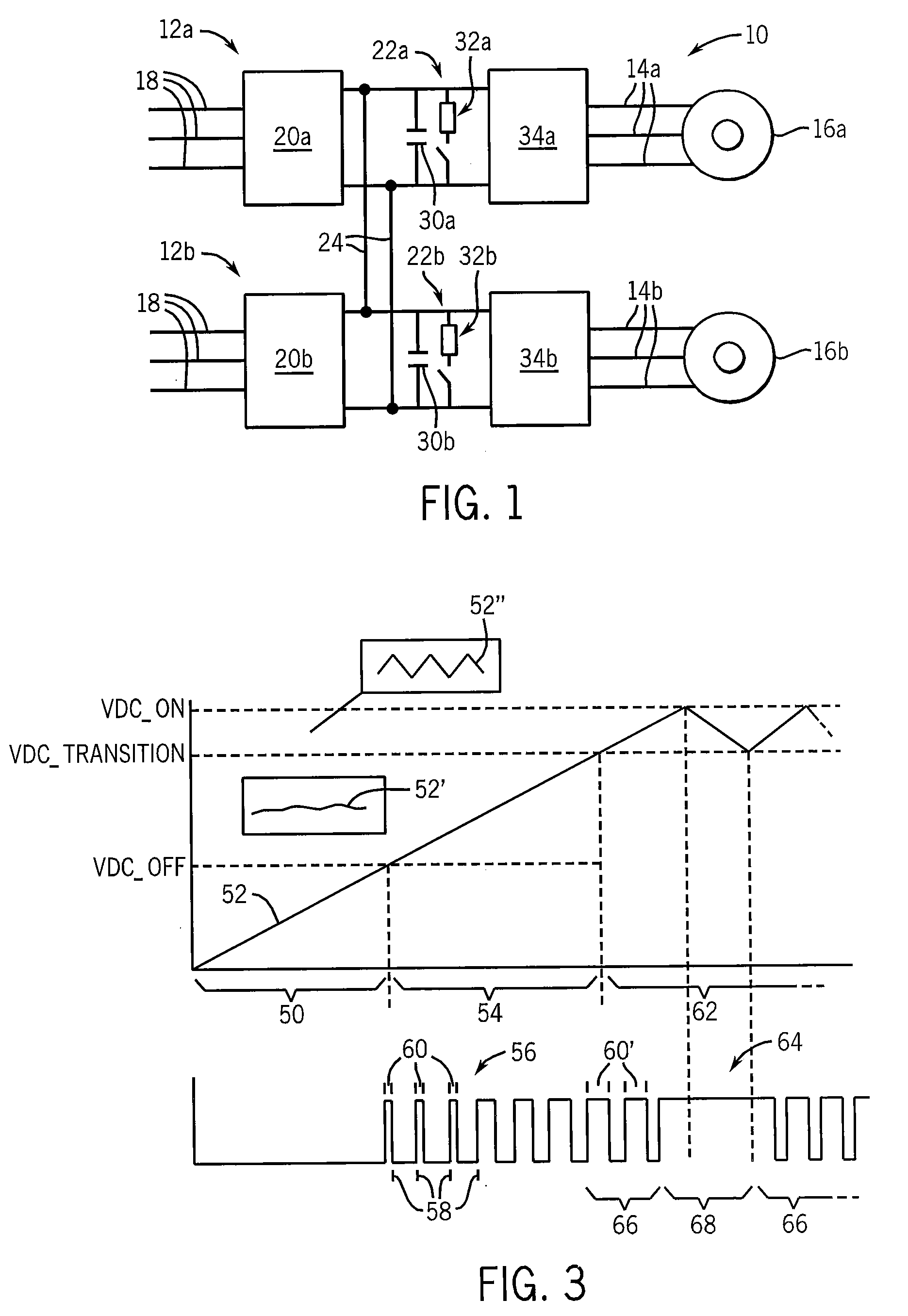
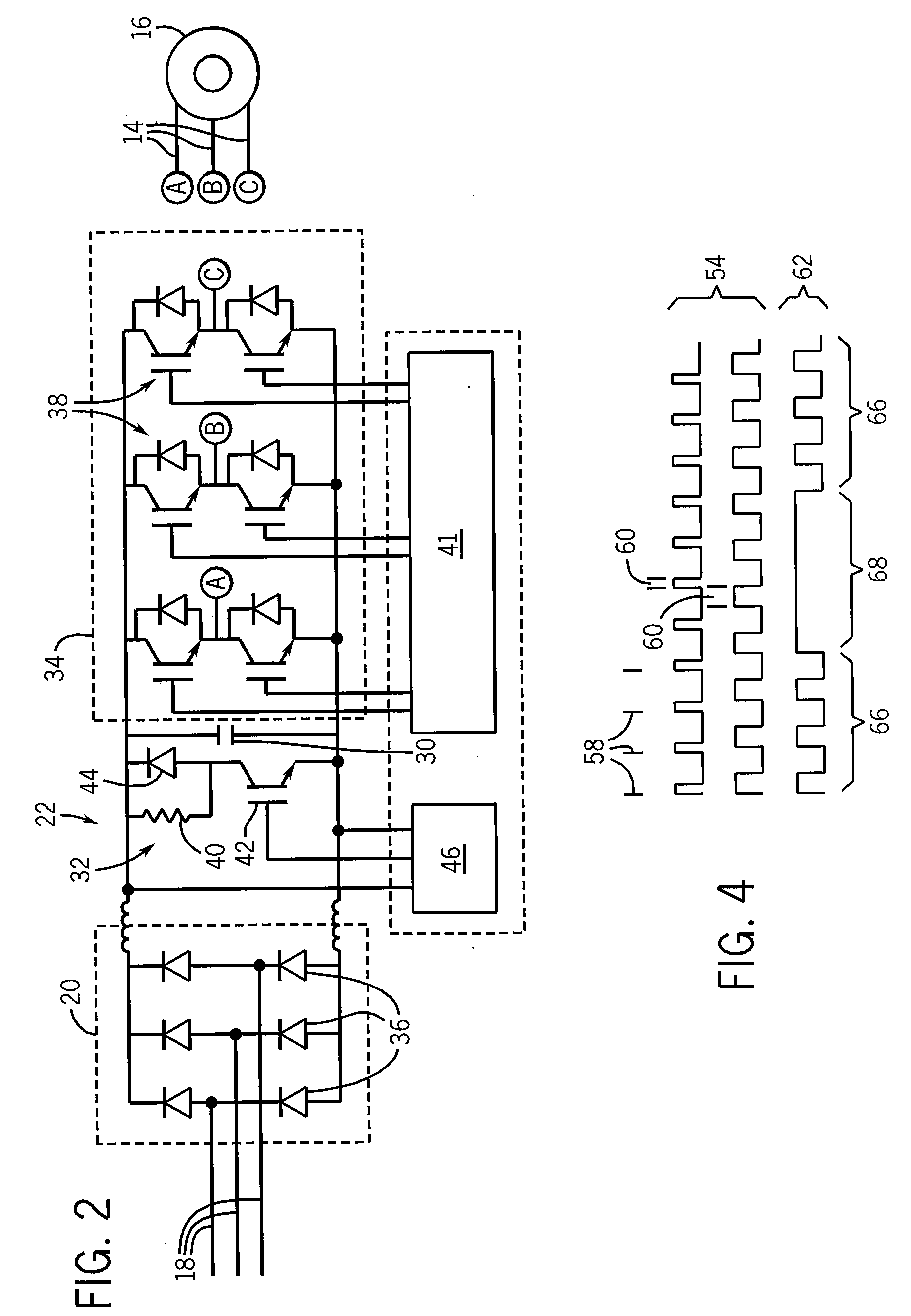
[0035]Referring now to FIG. 1, a motor control system 10 may include a first motor drive 12a and a second motor drive 12b each providing controlled three-phase power 14a and 14b to respective motors 16a and 16b. The motors 16a and 16b may, for example, be 50 hp or 15 hp motors drawing as much as 65 or 22 amps at approximately 460 VAC RMS or approximately 650 VDC. Referring to FIGS. 1 and 2, motor drives 12a and 12b may receive three-phase power 18 at respective rectifiers 20a and 20b to produce DC power on DC links 22a and 22b. Sometimes, the drives may also be used as a common DC bus configuration where its power is drawn from a common DC bus without rectifier circuit enabled. As shown in FIG. 2, the rectifier 20 may, for example, be a bridge of diodes 36 rectifying the three-phase power 18 into a high voltage (approximately 650 VDC) on the DC link 22. The DC links 22a and 22b may be shunted by link capacitors 30a and 30b respectively which provide for energy storage.

[0036]Power fr...


PUM


Abstract

A dynamic braking circuit for an electronic motor drive shunts the DC link of the drive with a resistor using two control strategies. The first control strategy used for lower levels of braking employs a pulse width modulated signal and the second control strategy used for higher levels of braking uses a hysteretic signal significantly reducing switching losses in the semiconductor devices controlling the dynamic braking resistor allowing higher braking capacity.

Description

STATEMENT REGARDING FEDERALLY SPONSORED RESEARCH OR DEVELOPMENT[0001]N / ACROSS REFERENCE TO RELATED APPLICATION[0002]N / ABACKGROUND OF THE INVENTION[0003]The present invention relates to dynamic motor braking systems working to control the speed of an electric motor by dissipating energy generated by the motor, and in particular to a braking system using a hybrid control strategy that offers greater braking capacity and improved operation of motor drives when connected in tandem.[0004]Motor drives control the frequency and amplitude of the electrical power applied to an electrical motor to improve motor operation, for example, by improving motor starting and stopping, motor speed and torque control, motor synchronization, load management, and energy efficiency. For this purpose, the motor drive will typically receive three-phase line power and rectify it to produce a DC bus voltage. The DC bus voltage is then received by a set of switching semiconductor devices, typically operating in...

Claims


Application Information

Patent Timeline
Patent Type & Authority Applications(United States)
IPC IPC(8): H02P3/06
CPCH02P3/12
Inventor THUNES, JERRY DEEWEI, LIXIANG
Owner ROCKWELL AUTOMATION TECH
Why Eureka
Try Eureka