Magnetic Resonance Imaging Apparatus

a magnetic resonance imaging and apparatus technology, applied in the direction of measuring using nmr, instruments, magnetic variable regulation, etc., can solve the problem that the intended image contrast may not necessarily be obtained, and achieve the effect of reducing sar, image contrast, and preventing the heating

Inactive Publication Date: 2009-10-08
HITACHI LTD
View PDF13 Cites 6 Cited by
  • Summary
  • Abstract
  • Description
  • Claims
  • Application Information

AI Technical Summary

Benefits of technology

[0015]According to the present invention, it becomes possible to obtain image contrast comparable to that obtainable with a constant flip angle, while preventing the heating effect by RF pulse irradiation, by maintaining the flip angle to be not larger than a certain value.
[0016]SAR corresponds to RF irradiation power per unit time. Therefore, in order to reduce SAR, it is necessary to lengthen the repetition time TR or to make the flip angle small. However, it is not preferable to change TR, since TR strongly affects the contrast of water and fat. Therefore, the flip angle is made small. In this case, if the flip angle is simply made small, contrast is degraded. Therefore, the flip angle is modulated within a range of values not larger than a flip angle providing desired image contrast as the upper limit to reduce SAR with maintaining image contrast.
[0017]In particular, when an imaging method includes execution of a non-imaging mode, image contrast is determined by a steady state attained in the non-imaging mode. Therefore, by defining the maximum value of the flip angle of magnetization (certain value) used in the imaging mode with the flip angle used in the non-imaging mode, an image can be obtained with favorable image contrast. This SAR reducing effect is especially more significant for a phase compensation type GrE pulse sequence using a large flip angle and short TR.
[0018]Moreover, a means for correcting influence of the modulation of the flip angle on image quality may be used in the present invention, and this enables provision of an image of still more favorable image quality.

Problems solved by technology

Therefore, even if only flip angle of an RF pulse for generating an echo having a small phase encoding amount is made large according to the prior art 1, intended image contrast may not necessarily be obtained.

Method used


Image

  • Magnetic Resonance Imaging Apparatus
  • Magnetic Resonance Imaging Apparatus
  • Magnetic Resonance Imaging Apparatus

Examples


first embodiment

[0048]According to this embodiment, by changing the flip angle of the RF pulse in the imaging mode in a range of values not larger than the value determined by the flip angle used in the non-imaging mode like the first embodiment, SAR can be reduced, and a favorable image not only free from degradation of image contrast, but also free from influence of flip angle modulation such as unsharpness and enhancement of edges can be obtained.

BRIEF DESCRIPTION OF THE DRAWINGS

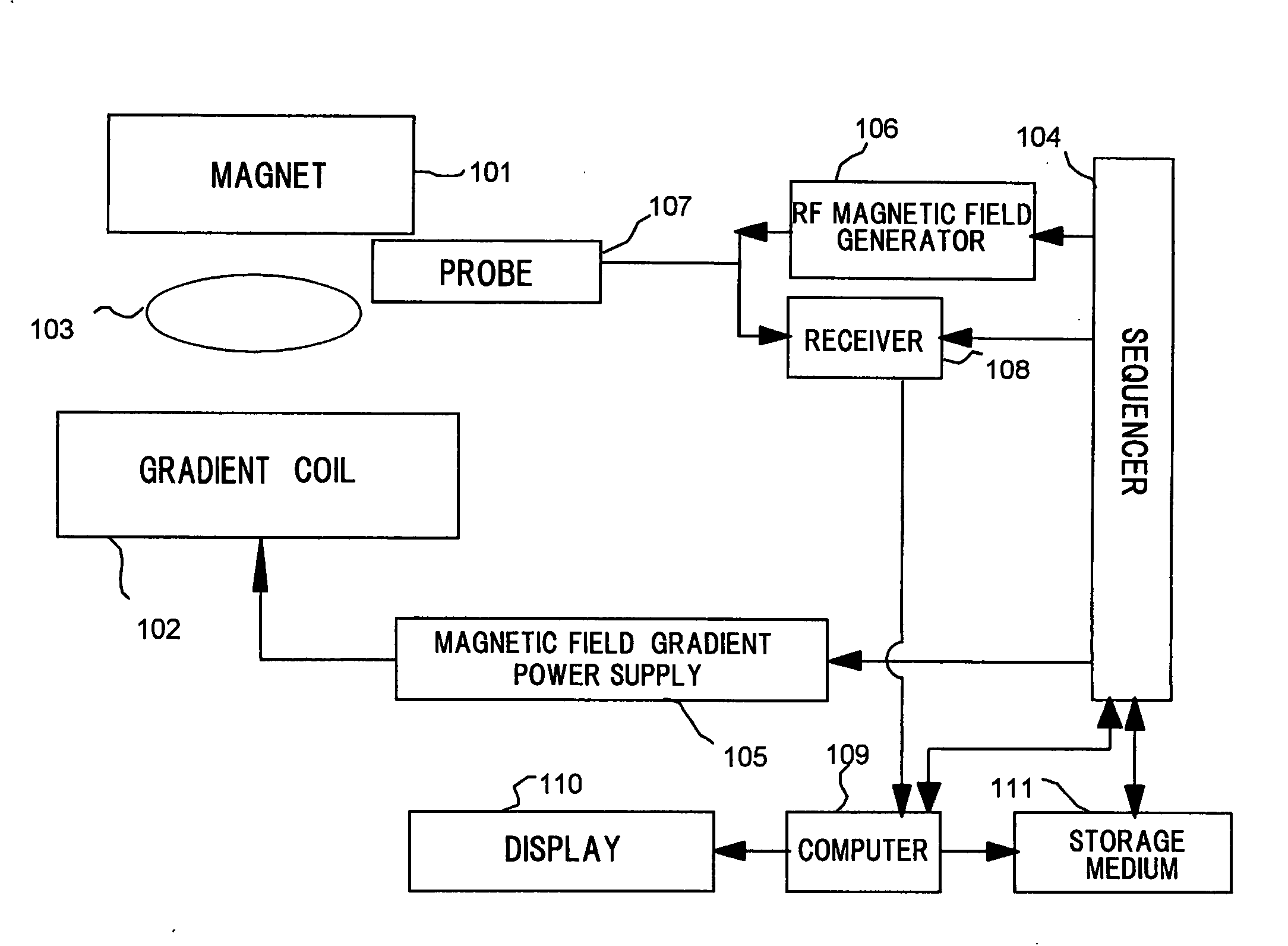
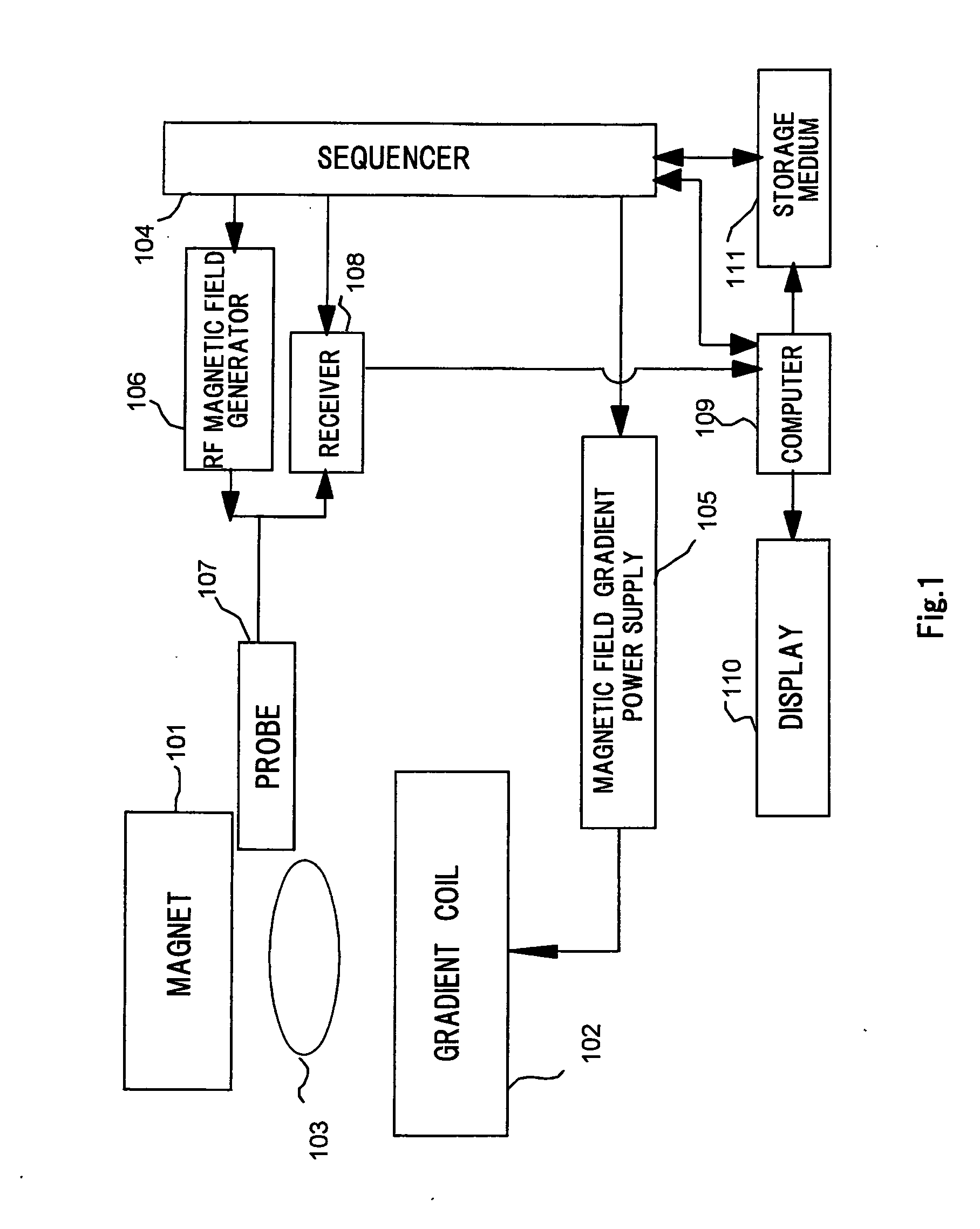
[0049]FIG. 1 A block diagram showing total configuration of an MRI apparatus to which the present invention is applied.

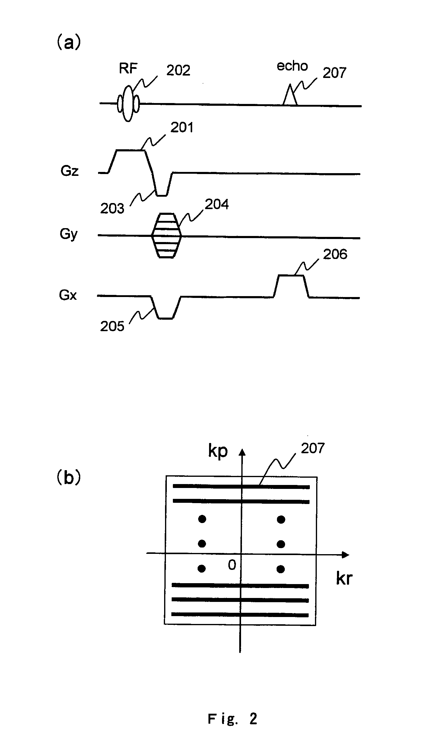
[0050]FIG. 2 A drawing showing a pulse sequence for the gradient echo method and k-space.

[0051]FIG. 3 A drawing showing a pulse sequence for the phase compensated type gradient echo method.

[0052]FIG. 4 A drawing showing details of control by a sequencer.

[0053]FIG. 5 A drawing showing flip angle and imaging results for one embodiment of the present invention.

[0054]FIG. 6 A drawing showing flip angles and ...

second embodiment

[0058]FIG. 10 A drawing for explanation of imaging according to the present invention.

EXPLANATION OF NUMERAL SYMBOLS

[0059]101 . . . Magnet for generating static magnetic field, 102 magnetic field gradient coil, 103 . . . test subject, 104 . . . sequencer, 105 . . . magnetic field gradient power supply, 106 . . . radio frequency magnetic field generator, 107 . . . probe, 108 . . . receiver, 109 . . . computer, 110 . . . display, 111 . . . storage medium.


PUM


Abstract

The MRI apparatus of the present invention executes a non-imaging mode 501 for obtaining a steady state of magnetization and an imaging mode 502 for measuring echoes for images. In the non-imaging mode 501 and the imaging mode 502, imaging is performed by using a GrE type pulse sequence. In the imaging, RF pulses are irradiated while flip angle of nuclear magnetization in the imaging mode 502 is changed in a range of values not larger than a certain value determined by flip angle of nuclear magnetization used in the non-imaging mode 502 is irradiated. This certain value is, for example, the maximum value of flip angle of nuclear magnetization used in the non-imaging mode, or flip angle provided by an RF pulse used at the end of the non-imaging mode. SAR observed with use of a GrE type pulse sequence can be thereby reduced without degrading image contrast, and thus influence on human bodies can be reduced.

Description

TECHNICAL FIELD[0001]The present invention relates to a magnetic resonance imaging technique.BACKGROUND ART[0002]Nuclear magnetic resonance imaging (MRI) apparatuses are diagnostic imaging apparatuses for medical use that induce nuclear magnetic resonance in nuclei of hydrogen atoms contained in an arbitrary plane traversing a test subject, and produce a tomographic image of a region in the plane using generated nuclear magnetic resonance signals. In general, when a slice magnetic field gradient for specifying imaging slice is applied, an excitation pulse is applied in order to excite magnetizations in the plane at the same time. Nuclear magnetic resonance signals (echoes) generated in the course of the precession of the magnetizations excited by the pulses. Positional information is imparted to the echoes by the magnetic field gradient, and Fourier transform of the echoes is performed to reconstruct images. The angle of inclination of the magnetization with respect to the direction...

Claims


Application Information

Patent Timeline
Patent Type & Authority Applications(United States)
IPC IPC(8): G01R33/54G01R33/28
CPCA61B5/055G01R33/586G01R33/5613G01R33/543
Inventor TANIGUCHI, YOOCHI, HISAAKI
Owner HITACHI LTD
Why Eureka
Try Eureka