Cryogenic storage container

a technology for cryogenic storage containers and storage containers, applied in the direction of containers, discharging methods, laboratory glassware, etc., can solve the problems of limited approach, waste of materials, time-consuming, etc., and achieve the effect of reducing the risk of cross-contamination, preventing spillage or contamination, and simplifying the handling and processing of biological specimens

Inactive Publication Date: 2009-10-15
FUJA TANNIN J
View PDF3 Cites 24 Cited by
  • Summary
  • Abstract
  • Description
  • Claims
  • Application Information

AI Technical Summary

Benefits of technology

[0007]The present invention relates to a disposable storage container that not only can be used to cryopreserve and store biological specimens at cryogenic temperature but also can be used directly in centrifuges or microcentrifuges to process biological materials. It incorporates the functions of both storage container and centrifuge tubes. With the present invention, handling and processing of biological specimens can be simplified. Instead of using as many as three or more devices, only a single device is needed. Pipetting samples from storage container to centrifuge tubes is eliminated. Moreover, the inventive container is designed with a cap, which seals the specimen within the vessel body to prevent spillage or contamination during the cryopreservation and the centrifugation processes. The potential risk of cross-contamination is reduced to a minimum. Furthermore, the container disclosed herein can provide higher cooling rates and higher warming rates for cryopreservation, resulting in higher viability and survival rate of biospecimens during cryopreservation and processing. In addition, the present invention is capable of standing upright on a flat surface without a separate support, the feature lacking in typical centrifuge tubes.

Problems solved by technology

Some limitations of this approach exist.
Moreover, it is time consuming and materials are wasted because each device has to be disposed once used.
This procedure also increases the potential risk of cross-contamination, particularly when processing several samples at the same time.
Nonetheless, this approach is one of the most common procedures performed in research and clinical laboratories because the existing products are not ideal for both cryopreservation as well as centrifugation.
Cooling can be more complicated.
Increase of cooling rate by one order will reduce the required cryoprotectants by 1 M. Since cryoprotectants, especially at high concentration, are typically toxic and can cause osmotic injuries, vitrification achieved by high cooling rate and less concentration cryoprotectants will result in higher viability and survival rate.

Method used


Image

  • Cryogenic storage container
  • Cryogenic storage container
  • Cryogenic storage container

Examples


Embodiment Construction

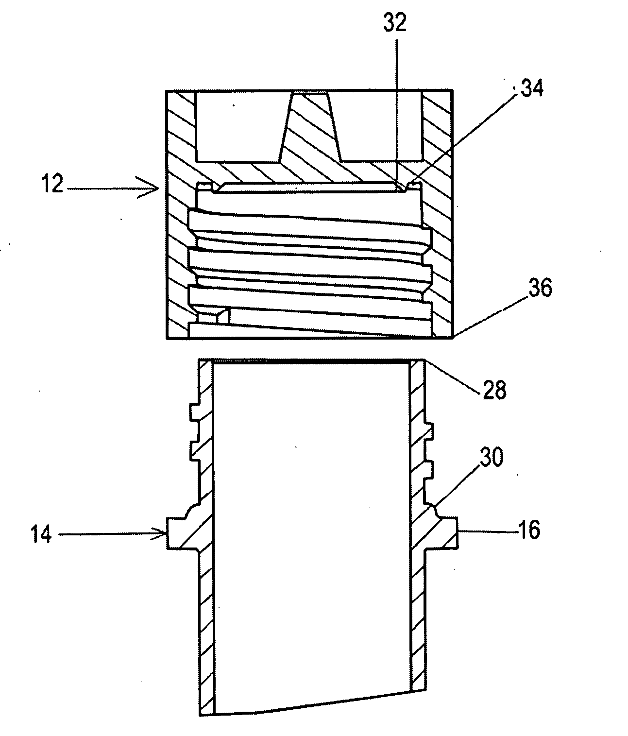
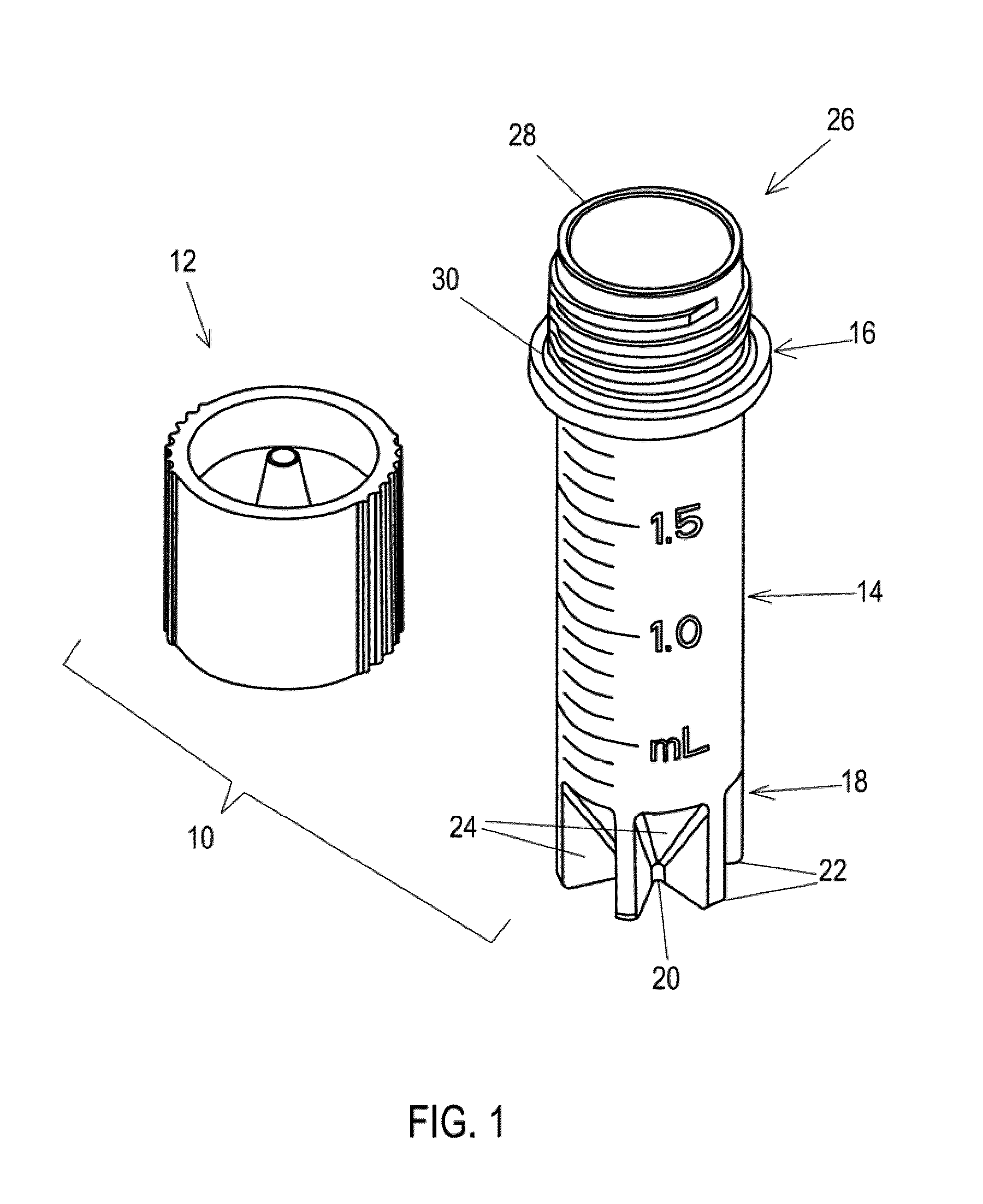
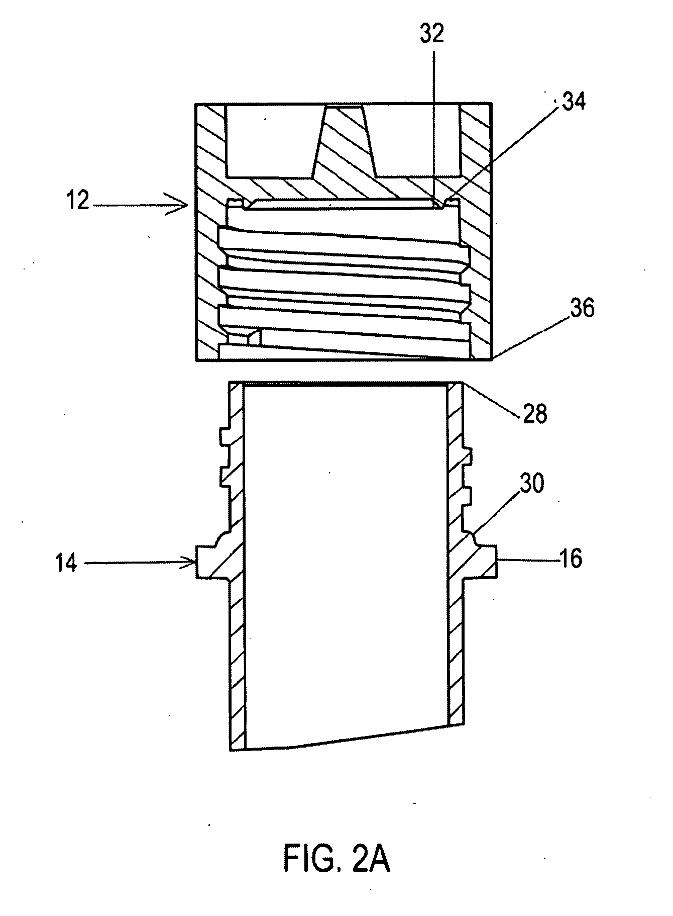
[0011]In one embodiment of the invention, shown in FIG. 1, a cryogenic storage container (10) includes a cap (12) and a vessel body (14). In the illustrated embodiment, a flange (16) is provided on vessel body (14) and a specialized bottom end (18) is formed in vessel body (14).

[0012]As shown in FIG. 1, the illustrated bottom end (18) is tapered so as to lead to a narrower tip (20). It is contemplated that tip (20) may be rounded or pointed. However, a plurality of fins (22) are positioned at bottom end (18) so as to provide, among other things, a stand that supports container (10) when it is positioned to stand on its bottom end (18) and better heat transfer capabilities during cooling and thawing steps in the cryopreservation process.

[0013]Between fins (22) at the bottom end (18) forms multiple vapor passages (24). Vapor passages (24) provide pathways to release vapor formed during cryopreservation. As such, it reduces vapor accumulation and vapor insulation layer at the bottom of...


PUM


Abstract

A cryopreservation storage and processing container for cryogenic material is disclosed. In one embodiment, the container can be used to cryopreserve and store biological specimens at cryogenic temperature but also can be used directly in centrifuges or microcentrifuges to process biological materials. It incorporates the functions of both storage container and centrifuge tubes, provides self-sealing mechanism, and accommodates higher cooling/warming rates. The storage container includes both a vessel body 14 and a cap 12.

Description

RELATED APPLICATIONS[0001]This application claims the benefit of U.S. Provisional Patent Application Ser. Nos. 61 / 044,997, filed 15 Apr. 2008. The following U.S. Provisional Patent Applications are incorporated by reference into this present non provisional application, 61 / 046,706, filed 21 Apr. 2008 and 61 / 087,705, filed 10 Aug. 2008.BACKGROUND OF THE INVENTION[0002]Biology, biochemistry immunology, and biotechnology often rely on the cryopreserved biological specimens for research, clinical and therapeutic developments. In the typical laboratory practice, the biological specimen is frozen in a cryovial and stored in a cryogenic freezer or dewar for a period of time. At the point of usage, the pre-cryopreserved specimen stored in the cryovial is taken from the freezer or dewar, and thawed in a warm water bath. After thawing, the solution is removed by a pipette and put into a centrifuge tube. The tube is then placed in a rotor and centrifuged to separate solid particles, such as ce...

Claims


Application Information

Patent Timeline
Patent Type & Authority Applications(United States)
IPC IPC(8): F17C1/00B65D25/00B65D41/04F25B19/00
CPCA01N1/0242A01N1/0257B01L3/5021A01N1/0268B01L2300/042B65D25/56B01L7/50
Inventor FUJA, TANNIN J.
Owner FUJA TANNIN J
Why Eureka
Try Eureka