Suspended tm mode dielectric combline cavity filter

a cavity filter and dielectric technology, applied in the field of combline filters, can solve the problems of poor filter quality factor, limited pattern of electromagnetic waves, and inability to support any tem mode signal, and achieve the effect of simple structure and same performan

Active Publication Date: 2009-10-15
ALCATEL LUCENT SAS
View PDF11 Cites 17 Cited by
  • Summary
  • Abstract
  • Description
  • Claims
  • Application Information

AI Technical Summary

Benefits of technology

[0015]In various exemplary embodiments, a combline filter achieves the same performance as a conventional combline filter without the need to attach the resonator to the housing with solder. This results in a much simpler structure. Thus, in various exemplary embodiments instead of coating the ceramic resonator ...

Problems solved by technology

Because this cavity acts as a waveguide, the pattern of electromagnetic waves is limited to those waves that can fit within the walls of the waveguide.
Although a TEM mode could theoretically exist in a waveguide with perfectly conducting walls, real cavity resonators have lossy walls so they cannot support any TEM mode signals.
If the central resonator in a combline filter is metallic, the filter's Quality factor, commonly called the Q-factor, will be poor.
This connection often...

Method used


Image

  • Suspended tm mode dielectric combline cavity filter
  • Suspended tm mode dielectric combline cavity filter
  • Suspended tm mode dielectric combline cavity filter

Examples


Embodiment Construction

[0030]Referring now to the drawings, in which like numerals refer to like components or steps, there are disclosed broad aspects of various exemplary embodiments.

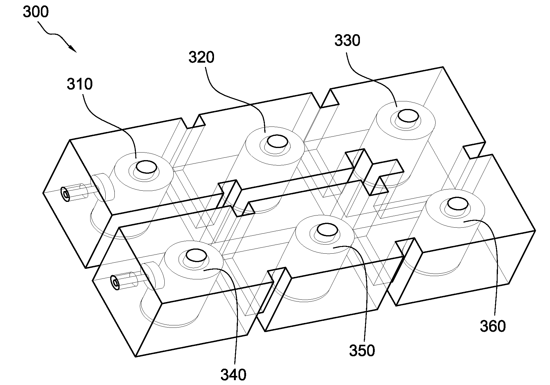
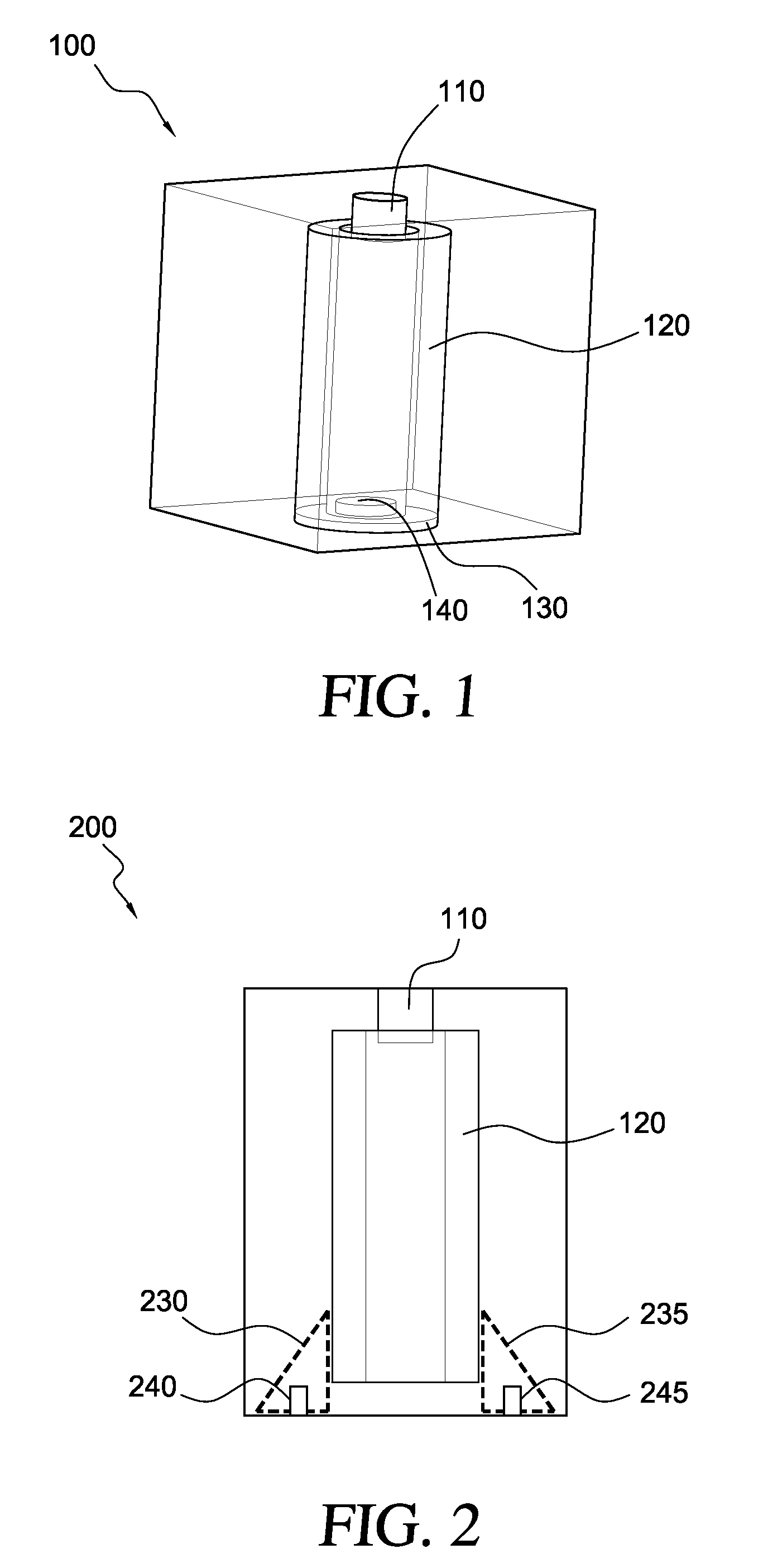
[0031]FIG. 1 is a perspective view of an exemplary suspended TM mode dielectric combline cavity 100. In various exemplary embodiments, cavity 100 includes a tuning element 110, a resonator 120, a support disk 130, and amounting element 140. Cavity 100 is defined by at least one electrically conductive wall. In various exemplary embodiments, such walls may either be metallic or made from a metallized polymer.

[0032]In various exemplary embodiments, cavity 100 has the shape of a rectangular parallelepiped. Thus, cavity 100 may consist of a top side, a bottom side, and four side walls. As will be appreciated by those skilled in the art, cavity resonators may be fabricated in shapes other than rectangular parallelepipeds, such as spheres and cylinders.

[0033]In various exemplary embodiments, a tuning element 110 extends downward ...


PUM


Abstract

A combline filter has a ceramic resonator disposed inside at least one cavity wall. Because the resonator is implemented as a hollow rod, a tuning element may be inserted into an opening on the top of the rod to tune its frequency. A mounting element, inserted into an opening on the bottom of the rod secures its position inside a cavity resonator. Instead of soldering the resonator to the filter's walls, the resonator is supported above a bottom or side wall of the cavity resonator.

Description

BACKGROUND OF THE INVENTION[0001]1. Field of the Invention[0002]This invention relates generally to combline filters for microwave and radio frequency signals and, more particularly, to a structure for suspending a ceramic resonator above a cavity.[0003]2. Description of the Related Art[0004]Coaxial combline filters are widely used in wireless communication systems. More specifically, these devices are often employed to reject unwanted frequencies. When implemented as a bandpass filter, users can tune a combline filter to select a desired range of frequencies, known as a passband, and discard signals from frequency ranges that are either higher or lower than the desired range. The filters are commonly known as combline filters because they consist of a series of parallel structures that resemble the hair-combing teeth in a comb.[0005]A cavity resonator confines electromagnetic radiation within a solid structure, typically formed as a rectangular parallelepiped. Because this cavity a...

Claims


Application Information

Patent Timeline
IPC IPC(8): H01P1/205H01P7/04
CPCH01P7/10H01P1/2084
Inventor SALEHI, HAMID REZALUKKARILA, TEPPO M.
Owner ALCATEL LUCENT SAS
Why Eureka
Try Eureka