
Method for purification of silica particles, purifier, and purified silica particles

Active Publication Date: 2009-10-15
SUMCO CORP
View PDF3 Cites 0 Cited by
  • Summary
  • Abstract
  • Description
  • Claims
  • Application Information

AI Technical Summary

Benefits of technology

[0007]The present invention solves the above-described problems in the conventional purification method of a silica powder, and an objective of the present invention is to provide a treatment method having excellent purification effect, which enables to remove high ionic impurities in a silica powder for a short time, and a purification apparatus and a purified silica powder.
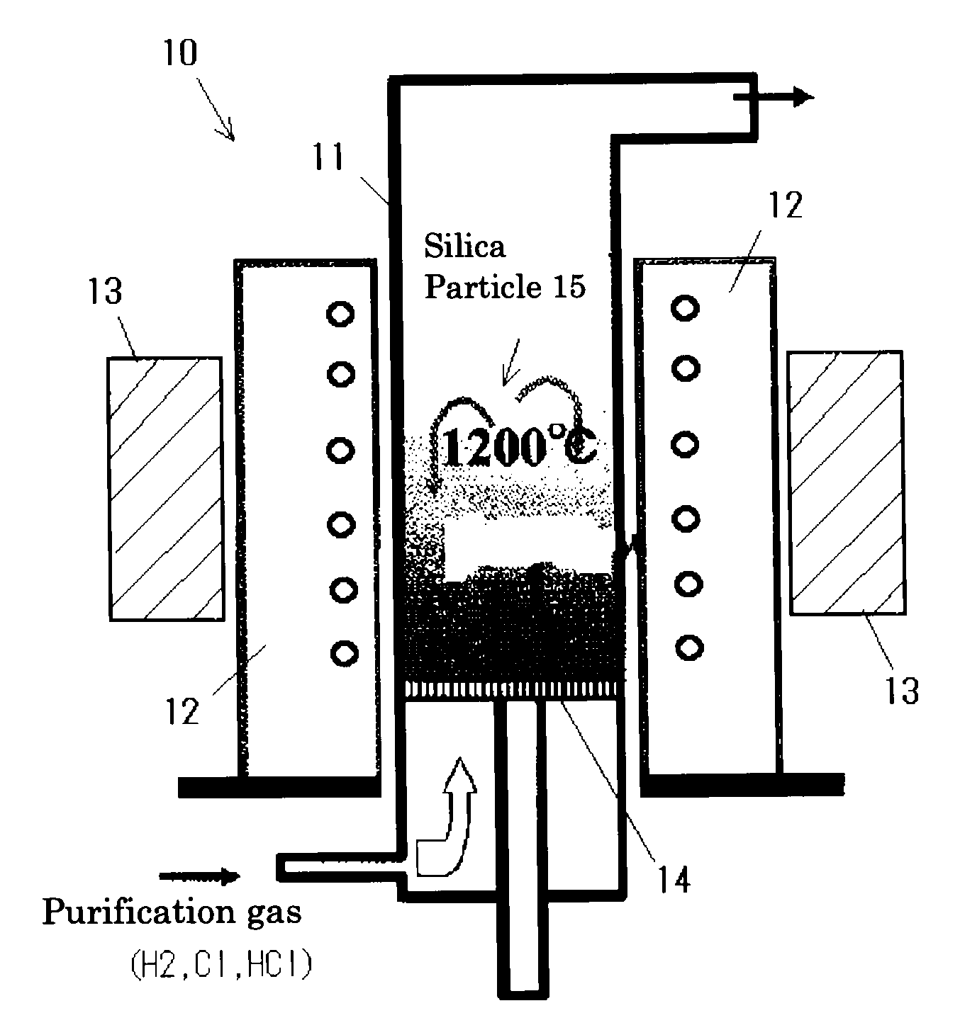
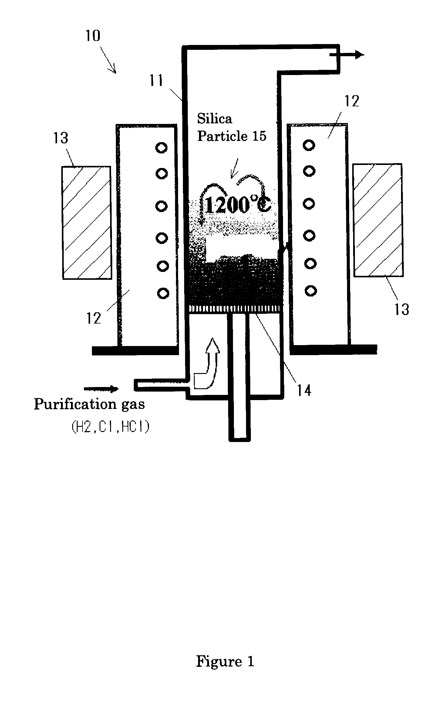
[0016]According to the purification method of the present invention, the silica powder in a fluid state is positioned within the magnetic field region in 10 gausses or more at a temperature of 1000° C. or more so as to be applied a voltage in an electric field generated by moving the silica powder, and contacted with the purification gas. Thus, ionic impurity components contained in the silica powder are induced by the electric field, diffused onto a powder surface, and easily reacted with the purification gas. Therefore, high purification effect can be obtained in a short time. The impurity components are reacted with the purification gas, and removed to an external of the system as gaseous compound.

Problems solved by technology

If impurities are contained in these silica powders, a semiconductor product is bad influenced so that the purified silica powder having few impurities is required.
However, although the method using hydrogen gas can purify for a short time, there are problems that controlling of gas concentration is difficult since hydrogen gas has dangerous of an explosive reaction, and handling of the hydrogen gas is also difficult.
On the other hand, although the method using chlorine gas or hydrogen chloride gas as the purification gas has high effect for removing impurities, it needs a long time for the purification.
Thus, there is a problem in productivity.
Further, the conventional electrolytic purification method also needs long treatment time.

Method used


Image

  • Method for purification of silica particles, purifier, and purified silica particles
  • Method for purification of silica particles, purifier, and purified silica particles

Examples


example

[0036]A silica powder was subjected to a purification treatment by the steps of: taking 20 kg silica powder having an average powder diameter of 220 μm into a quartz reaction container having an inner diameter of φ4250 mm; forming a fluid layer using air as carrier gas; forming a magnetic field in a fluid region; and inducing purification gas into the container at a high temperature (Example). In addition, a silica powder was subjected to the purification treatment by inducing the purification gas without forming the magnetic field in the fluid region (Comparison example). The effects by these treatments were shown in Table 1 in comparison. According to the example of the present invention, when the treatment time was 1 hour, each alkali metal content was 0.15 ppm or less, and partially 0.05 ppm or less. Especially, Li was largely removed. On the other hand, alkali metal contents of the comparison example were 0.3 ppm or more, and especially, Li was hardly removed.

TABLE 1MagneticImp...


PUM

PropertyMeasurementUnit
Temperatureaaaaaaaaaa

Abstract

[Problems] To provide a treatment method having excellent purification effect, in which impurities having high ionicity in a silica powder can be removed in a short time, a apparatus thereof, and a purified silica powder.[Means for Solving the Problems] A purification method of a silica powder comprises: making a silica powder into a fluid state; contacting a purified gas to the silica powder in the fluid state at high temperature; and thereby removing impurity components of the silica powder. In the method, the silica powder in the fluid state is positioned in a magnetic field region. Further, the silica powder is contacted with the purified gas, while applying voltage to the silica powder by an electric field generated by moving of the silica powder. Preferably, the silica powder in a fluid state is positioned in the magnetic region of 10 gausses or more, and contacted with the purification gas at a temperature of 1000° C. or more.

Description

FIELD OF THE INVENTION[0001]The present invention relates to a purification method of a silica powder, a purification apparatus thereof, and a purified silica powder.DESCRIPTION OF THE BACKGROUND ART[0002]A silica powder has been used as a raw material of a filler for a plastic package, such as IC, LSI and the like, or for a raw material powder of a quartz glass crucible for pulling up a silicon single crystal of a semiconductor material. If impurities are contained in these silica powders, a semiconductor product is bad influenced so that the purified silica powder having few impurities is required.[0003]As for a purification method of the silica powder, for example, Japanese Patent Application Laid Open No. 06-40713 discloses a method including: introducing gas containing chlorine or a chlorine compound into a silica powder at a temperature of 1000 to 1500° C. so as to fluidize the silica powder; and dehydrating the fluidized silica powder. Further, Japanese Patent Application Lai...

Claims


Application Information

Patent Timeline
IPC IPC(8): C01B33/12F27B15/14
CPCB01J8/1836B01J8/42B01J2208/00407B01J2208/00415B03C1/288C03C1/02B03C1/32B03C2201/16B03C2201/18C01B33/18B03C1/30C01B33/037
Inventor KANDA, MINORUTSUJI, YOSHIYUKI
Owner SUMCO CORP
Learn More