
Film insert molding (FIM) on a 3D shape

a 3d shape and film insert technology, applied in the field of film insert molding, can solve the problems of preventing the ability to over-mold the film on the outer side of the shell, affecting the ability to over-mold the film, and affecting the effect of the film insert, so as to prevent the film insert from wrinkling

Active Publication Date: 2009-10-22
GE LIGHTING SOLUTIONS LLC
View PDF15 Cites 28 Cited by
  • Summary
  • Abstract
  • Description
  • Claims
  • Application Information

AI Technical Summary

Benefits of technology

[0006]According to another aspect, a method of film insert molding of an article comprises generating a film insert, inserting the film insert into a mold, and injecting a viscous material into the mold, wherein the film couples to the material as the material cools and hardens. The ratio of a radius of curvature to diameter of the surface of the mold into which the film insert is placed is between approximately 1.5:1 and 10:1 to prevent the film insert from wrinkling.
[0007]According to another aspect, a film insert molding (FIM) system, comprises a flexible planar film having a shape that is congruent to a surface of an translucent traffic light shell, and a mold having the shape of the traffic light shell, into which the film is placed and viscous material is injected to form the traffic light shell, to which the film adheres as the viscous material cools. The surface of the mold has a ratio of a radius of curvature to diameter of an interior surface of the mold is within a predefined range of ratios to prevent wrinkling of the insert film, and the film provides protection from ultraviolet light and increases shell surface hardness.

Problems solved by technology

Testing of existing film insert molds has revealed two major problems.
First, when molding a shell that has a spherical surface, over-molding the film without folds on the outer portion is not possible using conventional systems and / or methods.
Second, the injection point is usually in the mold's cavity, impeding the ability to over-mold the film on the outer side of the shell.
Moreover, pre-shaping the film before over-molding it is not cost effective because it requires testing on different shapes in order to establish the minimum radius for the spherical surface and the maximum film thickness required.

Method used


Image

  • Film insert molding (FIM) on a 3D shape
  • Film insert molding (FIM) on a 3D shape
  • Film insert molding (FIM) on a 3D shape

Examples


Embodiment Construction

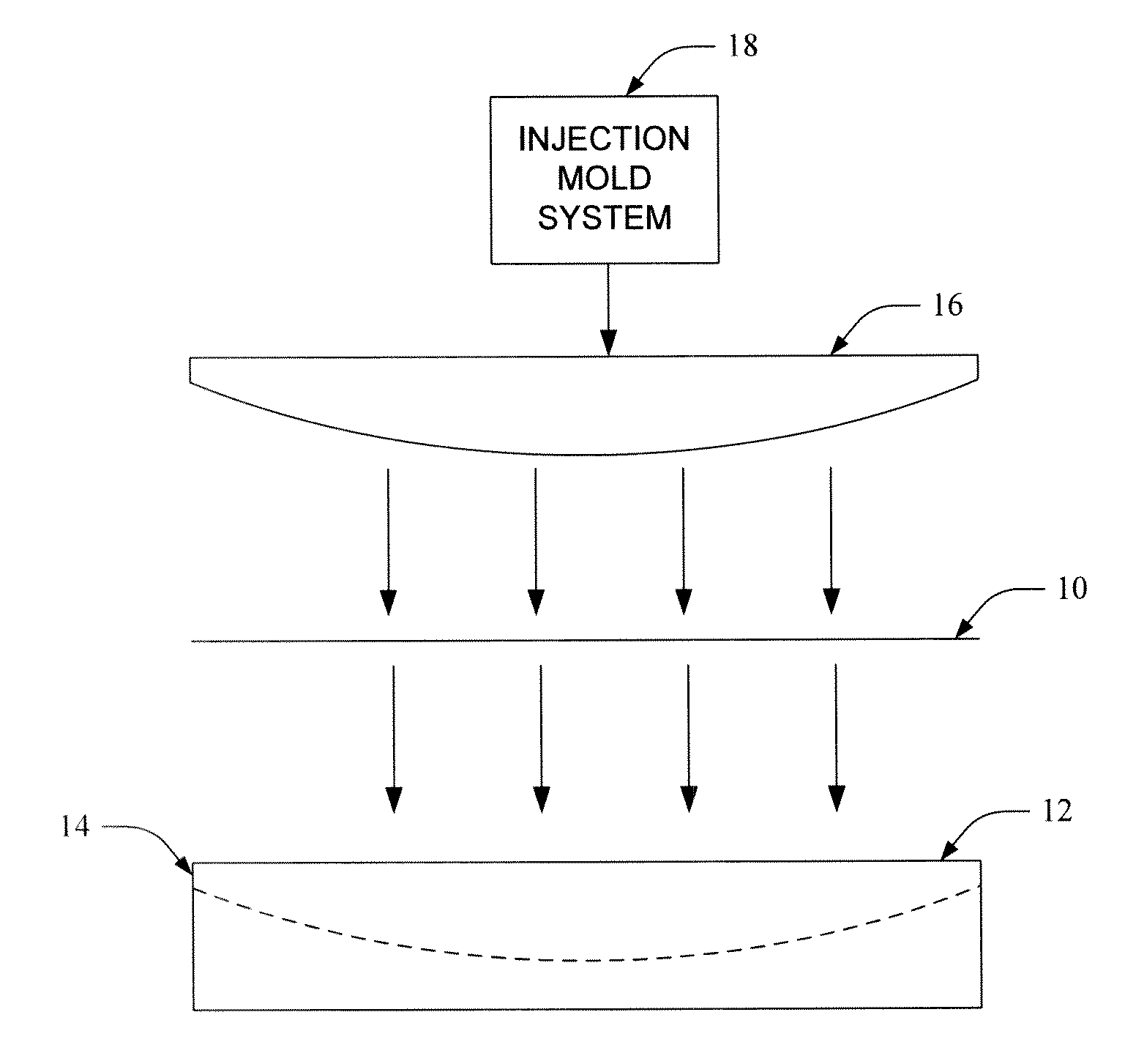
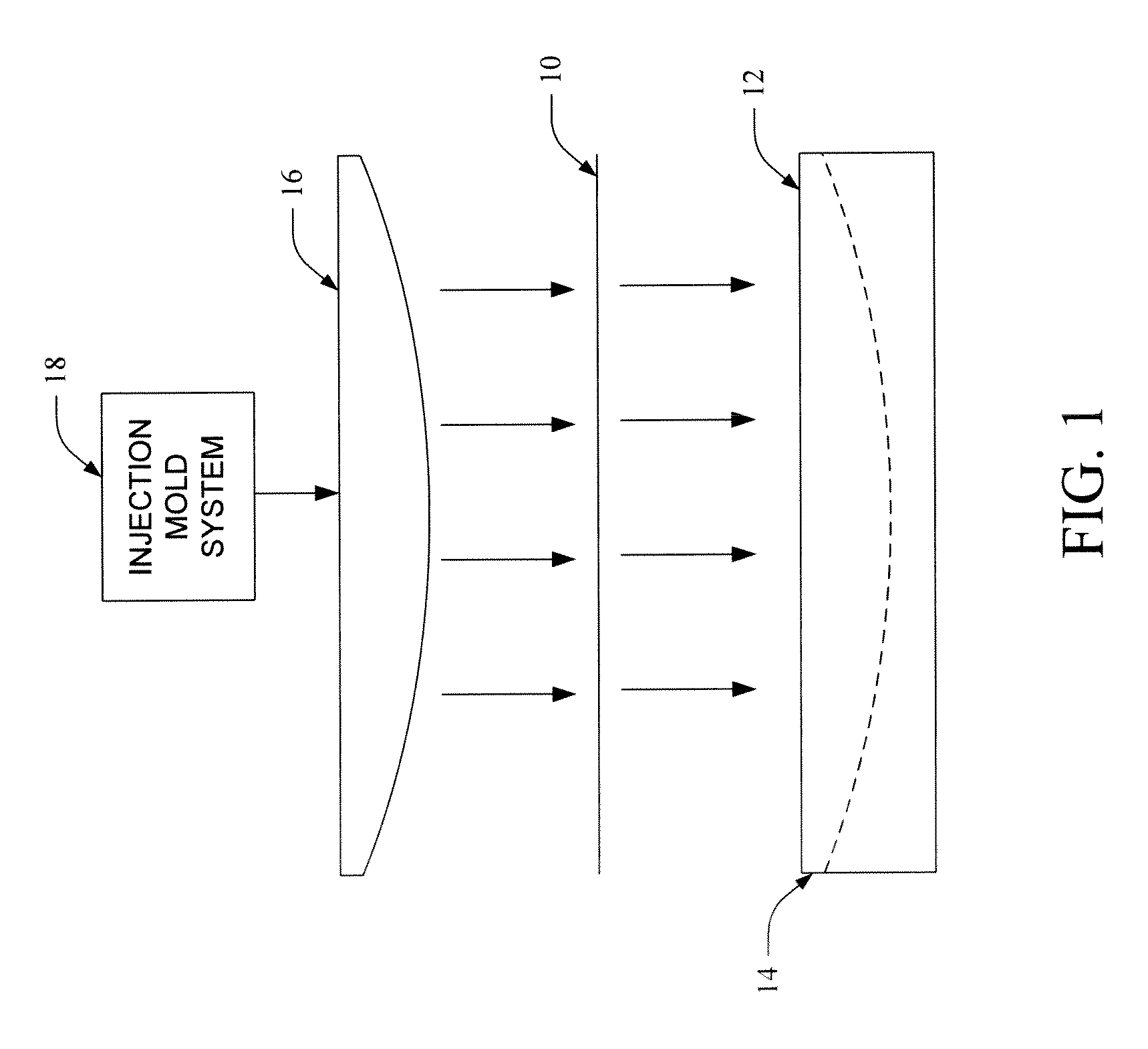
[0011]When manufacturing traffic light lenses or shells, a hard-coated shell surface is desirable for scratch resistance and to protect the shell plastic or polymer from degradation due to ultraviolet (UV) light. As the cost of the traffic light decreases, the cost of hard coating becomes significant. For instance, the cost of hard coating on an 8-inch traffic light shell may be approximately 10% of the total cost of the light. To reduce this cost, systems and methods are described for over-molding a thin film to generate a hard-coated surface on a spherical shape. While traditional methods involve two suppliers, such as a molder (e.g., a one-day process) and a coater (e.g., a 2-3 weeks' process), the subject innovation involves only a molding process, thereby reducing the cost associated with hard-coating by approximately 50% or more.

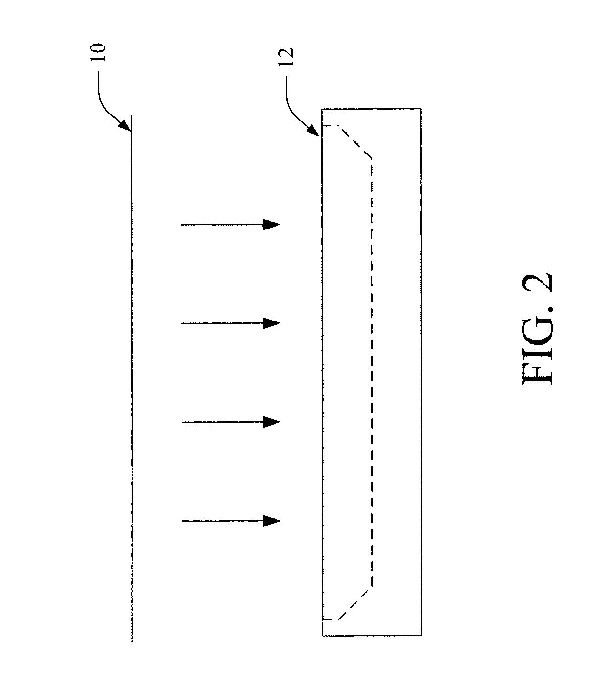
[0012]With reference to FIG. 1, a pre-cut, non-planar film insert 10 is shown, which is planar or three-dimensional (3D) in shape to fit a mold 12 int...


PUM

PropertyMeasurementUnit
Diameteraaaaaaaaaa
Electrical resistanceaaaaaaaaaa
Flexibilityaaaaaaaaaa

Abstract

Systems and methods are described for performing film insert molding (FIM) on a 3D shape, such as a traffic light shell or cover. A film is pre-generated for a surface to be covered by the film, and is inserted into a mold. A viscous material is then injected into the mold and the film bonds to the shell as the viscous material cools and hardens. The film includes a material selected to provide one or more of scratch resistance, improved shell hardness, UV protection, corrosion protection etc., and / or may be selected to alter optical characteristics of the shell.

Description

BACKGROUND[0001]The subject innovation relates to film insert molding (FIM). It finds particular application in conjunction with film insert molding on a three-dimensional (3D) shape, and will be described with particular reference thereto. However, it is to be appreciated that the described embodiments are also amenable to other applications.[0002]Options for generating a hard-coated surface (dipping, powder coating, FIM, etc.) require capital investment (paint shop set-up: ventilation, dust control, etc.). Of these, FIM is often the least expensive. Conventional FIM is a 3 steps process. First, the graphics are printed or coated on special high temperature films. Special inks are used that have been designed to endure the injection-molding environment. Next, the printed or coated appliqué can be formed into a 3D shape and cut to size for placement in the mold. Finally, the appliqué is placed in a mold cavity in which plastic is injected and the appliqué becomes integrated with the...

Claims


Application Information

Patent Timeline
IPC IPC(8): B29D11/00
CPCB29D11/0073
Inventor MARTINEAU, PATRICKDUBUC, EDENBOHLER, CHRISTOPHER L.
Owner GE LIGHTING SOLUTIONS LLC
Learn More