
Unitized Seal With Integral Spacer

a technology of sealing head and spacer, which is applied in the direction of sealing, vehicle cleaning, driving chains, etc., can solve the problems of contaminating the dynamic sealing surface of both mechanical face seal heads, significant chance of dirt getting into the sealed environment, and wear on one half of the outer surface of the bushings, so as to reduce friction, reduce adhesive wear, and minimize overall wear

Active Publication Date: 2009-10-22
FREUDENBERG NOK GEN PARTNERSHIP
View PDF29 Cites 5 Cited by
  • Summary
  • Abstract
  • Description
  • Claims
  • Application Information

AI Technical Summary

Benefits of technology

The seal assembly enhances the life of the sealing system by preventing contamination and maintaining the integrity of the lubricant, ensuring the drive train's longevity and reliability during field preventative maintenance.

Problems solved by technology

Track vehicles are typically operated and even have maintenance performed in very dirty environments in which there is a significant chance of contaminating dirt getting within the sealed environment.
In particular, chain preventative maintenance typically consists of dismantling each and every link in the chain and rotating the bushings 180 degrees to distribute wear from the drive sprockets, which only wear against one half of the outer surface of the bushings at a time.
With presently used seal designs, this assembly and re-assembly process inevitably contaminates the dynamic sealing surfaces of both the mechanical face seal head and the ends of the bushings that serve as the sealing counterface or seal seat for the seal.
After field preventative maintenance is completed, the contamination trapped between the mechanical face seal head and the bushing seal seat surface can separate these sealing surfaces and / or cause their abrasive destruction.
If the seals are destroyed, the seal's ability to retain lubricant internal of the seal and exclude external abrasives and liquids from entering the seal system and contaminating the lubricant is also destroyed.
The loss or contamination of the oil that lubricates between the drive bushing and link pins, in turn causes wear and failure of these components, and the drive train.

Method used


Image

  • Unitized Seal With Integral Spacer
  • Unitized Seal With Integral Spacer
  • Unitized Seal With Integral Spacer

Examples


Embodiment Construction

[0020]The following description of the preferred embodiment(s) is merely exemplary in nature and is in no way intended to limit the invention, its application, or uses.

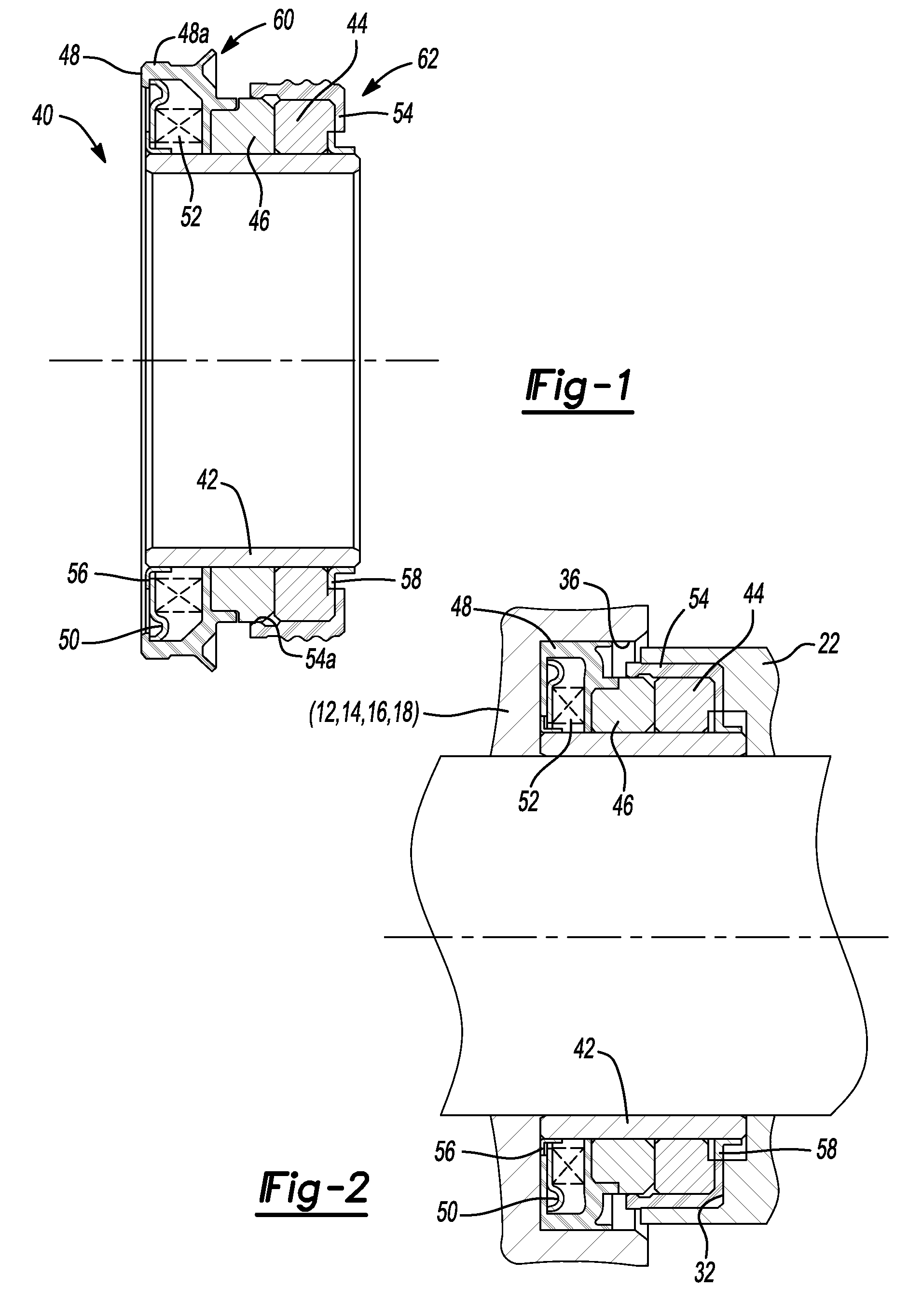
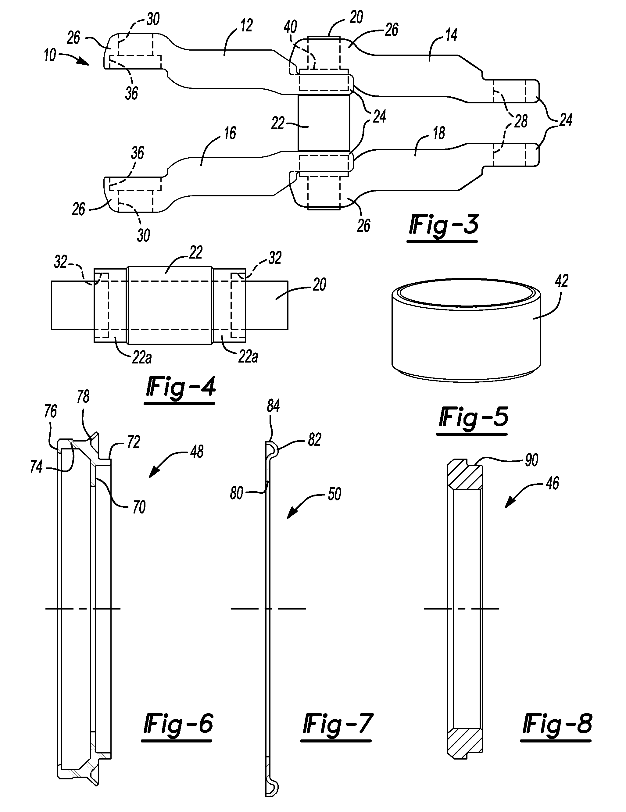
[0021]With reference to FIG. 3, a drive chain 10 is shown including identical links 12, 14, 16, 18 each mounted to a pin 20 and bushing 22. Each link 12, 14, 16, 18 includes an inner end 24 and an outer end 26. The inner end 24 includes an aperture 28 extending therethrough and sized for receiving the end portion 22a of bushing 22. The outer end 26 includes an aperture 30 extending therethrough and sized for receiving the pin 20 therein. The bushing 22 is provided with a recessed bore portion 32 and the outer end 26 of links 12, 14, 16, 18 include a recessed bore portion 34 which combine with bore portion 32 to define a chamber portion therebetween for receiving seal assembly 40, according to the principles of the present invention.

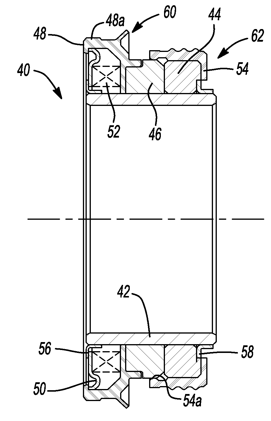
[0022]With reference to FIGS. 1 and 2, the seal assembly 40, according to the principle...


PUM


Abstract

A unitized seal assembly is provided for installation between linkages of a chain drive designed for tracked vehicles. The seal assembly facilitates field preventative maintenance on the drive chain by utilizing an integral spacer that holds the critical sealing surfaces together at all times, and has a seal head that can be easily removed from the outer link bore of a chain link. Removal of the seal head from the outer link bore causes as-installed clearance passageways between the seal head and seat portions and the spacer to forcefully close and prevent abrasive particles from getting inside the seal and reaching the interior interface junction of the dynamic sealing surfaces during seal maintenance. The seal assembly also includes additional sealing features that provide improved performance.

Description

CROSS-REFERENCE TO RELATED APPLICATIONS[0001]This application is a divisional of U.S. patent application Ser. No. 11 / 142,875 filed on Jun. 1, 2005. The entire disclosure of the above application is incorporated herein by reference.FIELD OF THE INVENTION[0002]The present invention relates to seal assemblies and more particularly to a seal assembly for use with chains used to drive a tracked vehicle.BACKGROUND AND SUMMARY OF THE INVENTION[0003]Drive chains are commonly used on vehicles having a track drive and typically include a chain bushing, a pin extending through the chain bushing and having an end projecting beyond the bushing and two chain links which are linked together by the pin and bushing on each side thereof. The chain links disposed on opposite sides of the chain bushing are overlapped in order to provide an inner chain link which is pressed onto the bushing and an outer chain link which is pressed onto the axially extending end of the pin.[0004]Drive chains of this type...

Claims


Application Information

Patent Timeline
Patent Type & Authority Applications(United States)
IPC IPC(8): B62D55/088
CPCB62D55/092B62D55/21F16J15/348F16J15/3452F16G13/07
Inventor DAHLHEIMER, JOHN C.
Owner FREUDENBERG NOK GEN PARTNERSHIP
Learn More