
Implant and method for facet immobilization

a technology of facet joint and implant, which is applied in the field of implant and method for immobilizing a vertebral facet joint, can solve the problems of further discomfort and pain, and achieve the effect of reducing motion

Active Publication Date: 2009-10-22
SPINAL ELEMENTS INC
View PDF14 Cites 189 Cited by
  • Summary
  • Abstract
  • Description
  • Claims
  • Application Information

AI Technical Summary

Benefits of technology

[0013]Various implants have been proposed for addressing facet degeneration by restoring motion, and often require bony resection to be placed within the spine. Alternatively, facet joints are often left untouched when adjacent vertebrae are fused together, which substantially reduces motion within the facet joints between the vertebrae. However, even slight motion within the degenerated facet joints can lead to further discomfort and pain.
[0014]Embodiments of the present invention provide a method and device for immobilizing a facet joint. The method and device allow maintenance of the relative spacing between the facets within the facet joint, while allowing each of the adjacent articular surfaces of the facet joint to fuse to an implant provided between the facets. Such immobilization of the facet joint can alleviate the bone on bone contact that is common in degenerative facet joints and which may be a source of pain or discomfort even when the adjacent vertebrae are fused together.

Problems solved by technology

However, even slight motion within the degenerated facet joints can lead to further discomfort and pain.
Such immobilization of the facet joint can alleviate the bone on bone contact that is common in degenerative facet joints and which may be a source of pain or discomfort even when the adjacent vertebrae are fused together.

Method used


Image

  • Implant and method for facet immobilization
  • Implant and method for facet immobilization
  • Implant and method for facet immobilization

Examples


Embodiment Construction

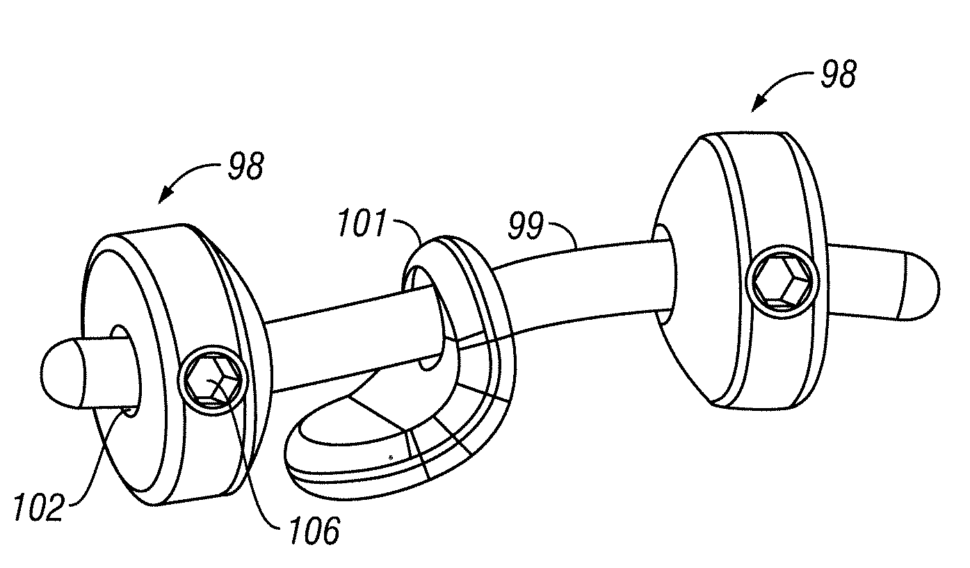
[0054]In one aspect, embodiments of the present invention provide a device for immobilizing a facet joint, and which can further maintain a spacing between the two facets of the immobilized facet joint. As shown in FIGS. 7A and 7B, the device includes an implant 34 with two faces: a first face 36 adapted to contact the articular surface of one facet of the facet joint and a second face 38 adapted to contact the articular surface of the other facet.

[0055]The implant can be formed from any of a variety of materials known in the art, including but not limited to a polymer such as polyetheretherketone (PEEK), polyetherketoneketone (PEKK), or polyethylene. Alternatively, the implant can be formed from a ceramic such as zirconia, alumina, or silicon nitride. The implant may also be formed from a metal including, but not limited to, titanium, a titanium alloy, cobalt chromium, or a stainless steel. The implant can also be formed from a wafer of allograft material or autograft material, whi...


PUM


Abstract

Devices and methods are provided for immobilizing facet joints of the vertebral column. Embodiments of the invention provide an implant that is inserted in a facet joint from which cartilage has been removed, and which retains the approximate original spacing of the facets in the joint. A retaining arrangement, such as an adhesive, a threaded fastener, or a screw is then used to secure the implant in the joint.

Description

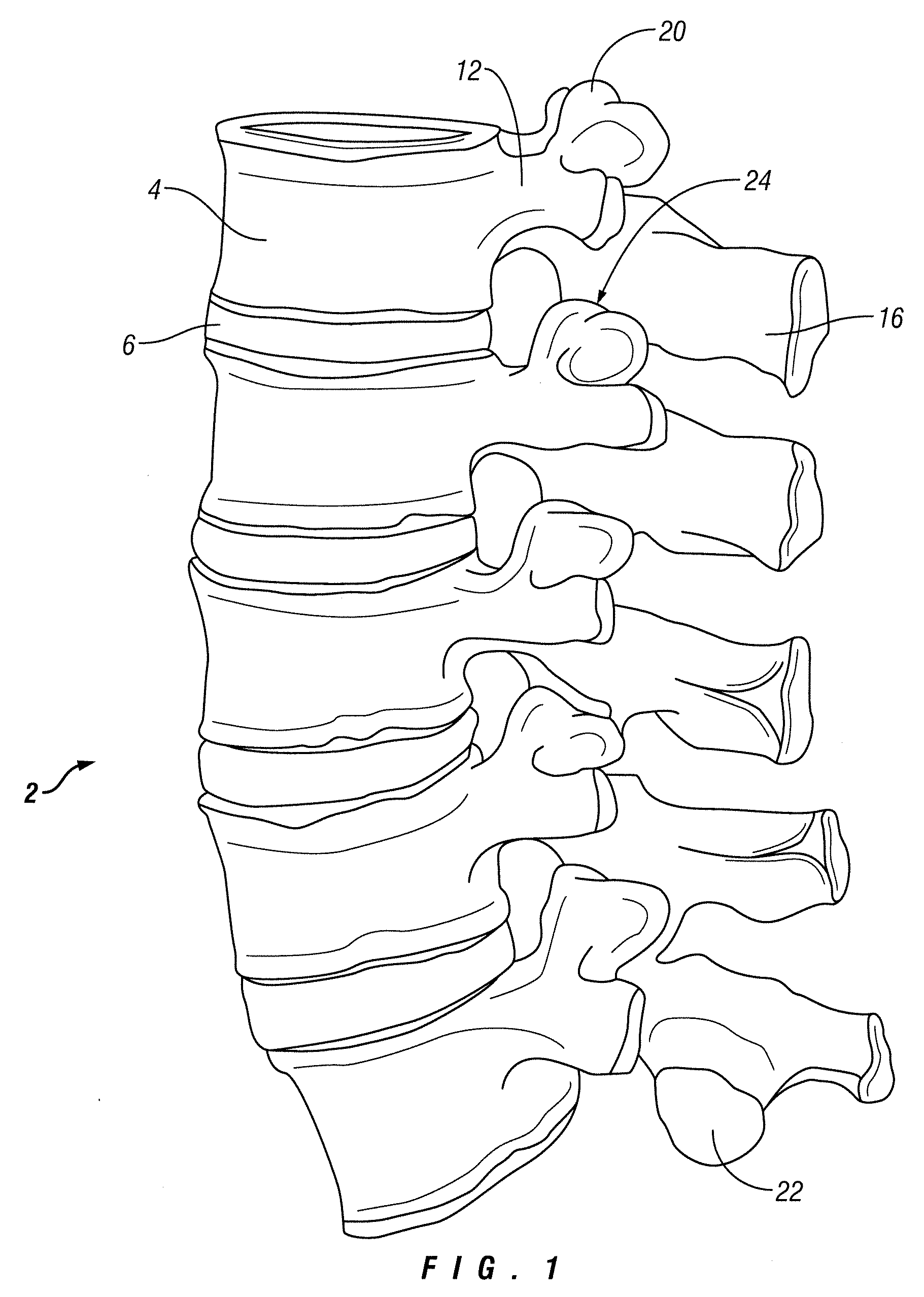
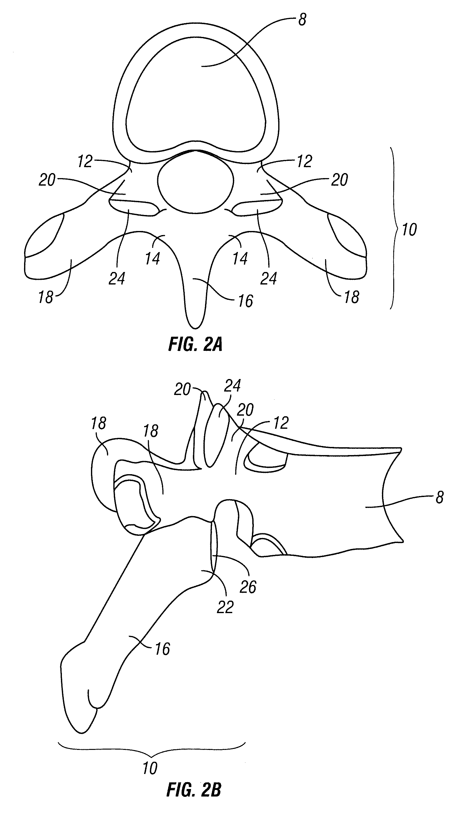
FIELD OF THE INVENTION[0001]The present invention relates to an implant and method for immobilizing a vertebral facet joint.BACKGROUND INFORMATION[0002]Traumatic, inflammatory, and degenerative disorders of the spine can lead to severe pain and loss of mobility. For example, back and spinal musculoskeletal impairments are significant causes of lost work productivity in the United States. Pain as a result of some type of spinal impairment may have its source in a variety of pathologies or clinical conditions.[0003]As shown in FIG. 1, the vertebral column 2 of the spine includes a series of alternating vertebrae 4 and fibrous discs 6 that provide axial support and movement to the upper portions of the body. The vertebral column 2 typically includes thirty-three vertebrae 4, with seven cervical (C1-C7), twelve thoracic (T1-T12), five lumbar (L1-15), five fused sacral (S1-S5) and four fused coccygeal vertebrae.[0004]FIGS. 2A and 2B depict a typical thoracic vertebra. Each vertebra inclu...

Claims


Application Information

Patent Timeline
IPC IPC(8): A61B17/70A61B17/04
CPCA61B17/7064A61F2310/00359A61F2/4405A61F2002/2821A61F2002/302A61F2002/30446A61F2002/30462A61F2002/30507A61F2002/30512A61F2002/30754A61F2002/30777A61F2002/30968A61F2220/0025A61F2220/0041A61F2220/0075A61F2230/0065A61F2310/00017A61F2310/00023A61F2310/00029A61F2310/00203A61F2310/00239A61F2310/00317A61F2/28A61F2002/30433
Inventor BLAIN, JASON
Owner SPINAL ELEMENTS INC
Learn More