Joined composite structures with a graded coefficient of thermal expansion for extreme environment applications

a composite structure and coefficient of thermal expansion technology, applied in the field of composite structures, can solve the problems of increasing design complexity, increasing cost, and difficulty in attaching members with dramatically different coefficients of thermal expansion for use in high and low temperature applications

Inactive Publication Date: 2009-10-29
THE BOEING CO
View PDF26 Cites 41 Cited by
  • Summary
  • Abstract
  • Description
  • Claims
  • Application Information

AI Technical Summary

Benefits of technology

[0008]A graded coefficient of thermal expansion (CTE) interface is provided by a composite structure having a first end for attachment to a structural component with a first CTE and a second end for attachment to a second structural component with a second CTE. Joining processes are employed to create a layered composite billet or near net shape with a graded CTE. The CTE-graded layered composite billet or near net shape is provided in a first embodiment by welding, in a second embodiment by brazing, and in a third embodiment by solid state joining. The resulting CTE-graded layered composite is then processed to produce a first surface for attachment of the first structural member having a first CTE and to produce a second surface for attachment of the second structural member having a second CTE. The resulting assembly provides capability for attaching structural members with vastly different CTE to produce an assembly that can be heated or cooled without introducing significant thermal stresses or strains. Additionally, the assembly does not rely on complicated mechanisms and complex designs to allow relative movement during heating or cooling, allowing for a substantially rigid solution tailored to inherently accommodate for the wide CTE mismatch.

Problems solved by technology

When exposed to the intended extreme environments, significantly high thermal stresses and strains may be developed, which may lead to undesirable results.
This has been an issue, which has either completely restricted the use of these advanced structural materials or has resulted in costs skyrocketing, whether it be for weight penalties or increase in complexity of designs to allow for attachment to available structural alloys.
Attaching members with dramatically different CTEs for use in high and low temperature applications is an extremely challenging task.
Existing solutions (which are usually not feasible if members have dramatically different CTEs) mainly involve complicated mechanical fastening devices, which are designed to allow relative movement between members with different CTEs when the assembly is heated or cooled.
This may result in complex connections.
Existing solutions tend to be non-rigid due to the fact that they may be inherently flexible to allow relative movement and they may have features that are not optimal for use in typical high temperature applications, such as engines, turbines, and vehicle leading edges.

Method used


Image

  • Joined composite structures with a graded coefficient of thermal expansion for extreme environment applications
  • Joined composite structures with a graded coefficient of thermal expansion for extreme environment applications
  • Joined composite structures with a graded coefficient of thermal expansion for extreme environment applications

Examples


example 1

[0090]Attachment of a ceramic matrix composite thruster chamber 150 to a titanium injector 152 in a rocket engine assembly as shown in FIG. 14B.

[0091]The most common material of construction of a rocket chamber is a silicide coated Nb alloy. The operating temperature limited to 2500 F (˜50% of combustion temperature) and fuel film cooling is employed to maintain this thermal limit. The use of extensive amounts of fuel film cooling may lead to undesirable results. The key to high performance is the combustion chamber material life limiting mechanisms. Another challenging issue for high performance is providing leak-free joints while attaching a combustion chamber to an injector. The combustion chamber operates at high temperatures while the injector needs to be maintained at low temperatures. Currently, Nb rocket chambers are welded directly to the injectors.

[0092]The use of ceramic matrix composite chambers can enable the design of higher performance rocket engines with reduced plum...

example 2

[0094]An alternative method for attachment of a ceramic matrix composite chamber 150 to a titanium injector 152 in a rocket engine assembly as shown in FIG. 14B is provided by stir welding of the layers for transition component 154.

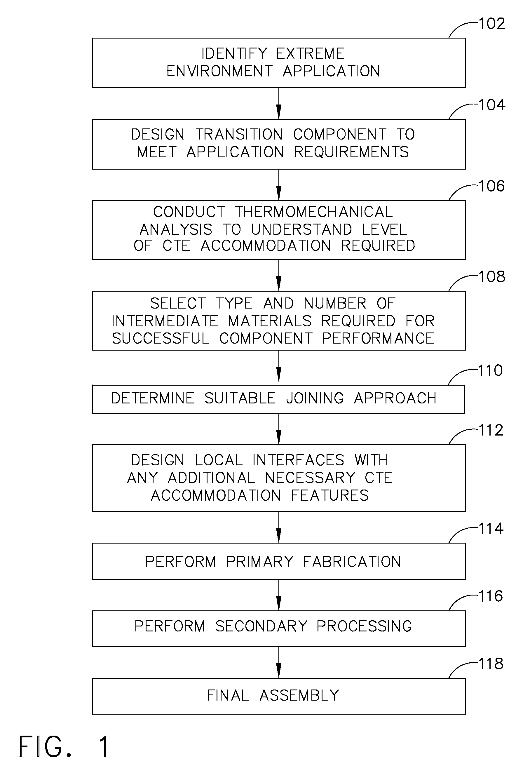
[0095]FIG. 15A describes the refinement of the generalized method for this example and is described with respect to the illustrations in FIGS. 6A and 6B and 15B. The method shown provides for assessment of the extreme environment application 1502, which for the example shown is the injector-chamber attachment component in a rocket engine with the injector fabricated from titanium and the chamber constructed from CMC. Component design 1504 is then accomplished providing a cylindrical interattchment ring which is to be EB-welded on one side to the titanium injector and brazed on the opposite side to the CMC chamber. A thermomechanical analysis is then undertaken 1506 which demonstrates a maximum temperature at the interface of approximately 1300 F and mecha...

example 3

[0097]Engine-nozzle attachment component 170 in aircraft as shown in FIG. 16B wherein an engine flange (attachment interface) 172 is made from Inconel 718 and a nozzle 174 is CMC.

[0098]Aircraft engines may offer better fuel economy by running the combustor section at higher temperatures. Metallic alloys conventionally used for the exhaust systems may have an undesirably short service life at the higher temperatures. Replacing the current metallic exhaust system with ceramic matrix composites may resolve this issue and may potentially help reduce weight. However, such a ceramic matrix composite exhaust system (very low CTE) should be designed to mate to a superalloy engine interface (very high CTE). Providing a leak-free attachment between the ceramic matrix composite nozzle and a superalloy flange (e.g. made of Inconel 718) is a challenge since they cannot be directly welded and other attachment options are not practical due to the dramatic CTE mismatch. The CTE mismatch can be addr...


PUM

PropertyMeasurementUnit
thicknessaaaaaaaaaa
temperatureaaaaaaaaaa
coefficient of thermal expansionaaaaaaaaaa

Abstract

An integrated composite structure with a graded coefficient of thermal expansion (CTE) is formed by selecting a plurality of layers of materials with a graded CTE and using joining approaches such as welding, brazing, or solid state bonding to produce a CTE-graded layered composite or near net shape. The integrated composite billet or near net shape is then processed to produce a first surface for attachment of a first structural member having a first CTE and to produce a second surface of for attachment of a second structural member having a second CTE.

Description

REFERENCE TO RELATED APPLICATIONS[0001]This application is related to co-pending patent application Ser. No. ______ having attorney docket no. 07-0323 entitled BUILT-UP COMPOSITE STRUCTURES WITH A GRADED COEFFICIENT OF THERMAL EXPANSION FOR EXTREME ENVIRONMENT APPLICATIONS filed substantially concurrently herewith having a common assignee with the present disclosure.BACKGROUND[0002]1. Field[0003]Embodiments of the disclosure relate generally to the field of structures for interattachment of materials and components with significantly differing coefficients of thermal expansion (CTE) and more particularly to a composite structure with constituents having a graduated CTE for connection of two structures with vastly different CTE and a method for creation of the graded CTE composite structure.[0004]2. Description of the Related Art[0005]The need for higher capability, weight efficient, and long lasting extreme environment structures has necessitated the use of higher capability advance...

Claims


Application Information

Patent Timeline
Patent Type & Authority Applications(United States)
IPC IPC(8): B23K20/12B23K31/02B64C1/00B32B7/027
CPCB32B7/02B32B2605/18C04B37/026C04B2235/72C04B2237/76C04B2237/122C04B2237/123C04B2237/403C04B2237/405C04B2235/9607C04B2237/58B32B7/027
Inventor YOUSEFIANI, ALICOMFORT, JOHN M.VOLLMER, JOHN G.HAND, MICHAEL L.
Owner THE BOEING CO
Why Eureka
Try Eureka