
Method of making transparent conductive film

a technology of transparent conductive film and conductive film, which is applied in the field of making transparent conductive film, can solve the problems of high cost, unsuitable for mass production, complicated equipment,

Active Publication Date: 2009-10-29
TSINGHUA UNIV +1
View PDF11 Cites 40 Cited by
  • Summary
  • Abstract
  • Description
  • Claims
  • Application Information

AI Technical Summary

Benefits of technology

[0006]The conventionally used transparent conductive film is an Indium-Tin oxide (ITO) thin film, which has a high electrical conductivity and a high transparency. Since the ITO is solid at room temperature, it can be easily etched to obtain a predetermined pattern. The method of patterning the ITO thin film is as follows. Firstly, depositing the ITO thin film on the substrate by the vacuum evaporation method or magnetron sputtering method, and then forming the ITO thin film with the pattern by ion plasma etching. The etching process for forming the predetermined pattern requires the ion plasma with a high energy, which is costly and needs a complicated equipment to carry out. Furthermore, the high energy accompanies with a high temperature, which is not suitable for the substrate with a low melting point. Additionally, since the patterning process needs using a strongly alkaline solution and HF solution to pre-treat and post-treat the ITO thin film, the process unavoidably will cause pollution to the environment.

Problems solved by technology

The drawbacks of these methods include complicated equipment, high cost and being not suitable for mass production.
Furthermore, these methods need a process of high-temperature annealing, which will damage a substrate on which the transparent conductive film is formed, whereby a substrate with a low melting point cannot be used for forming the film.
Thus, the conventional methods have their limitations.
The etching process for forming the predetermined pattern requires the ion plasma with a high energy, which is costly and needs a complicated equipment to carry out.
Furthermore, the high energy accompanies with a high temperature, which is not suitable for the substrate with a low melting point.
Additionally, since the patterning process needs using a strongly alkaline solution and HF solution to pre-treat and post-treat the ITO thin film, the process unavoidably will cause pollution to the environment.

Method used


Image

  • Method of making transparent conductive film
  • Method of making transparent conductive film
  • Method of making transparent conductive film

Examples


Embodiment Construction

[0013]Reference will now be made to the drawings to describe various embodiments of the present method of making a transparent conductive film, in detail.

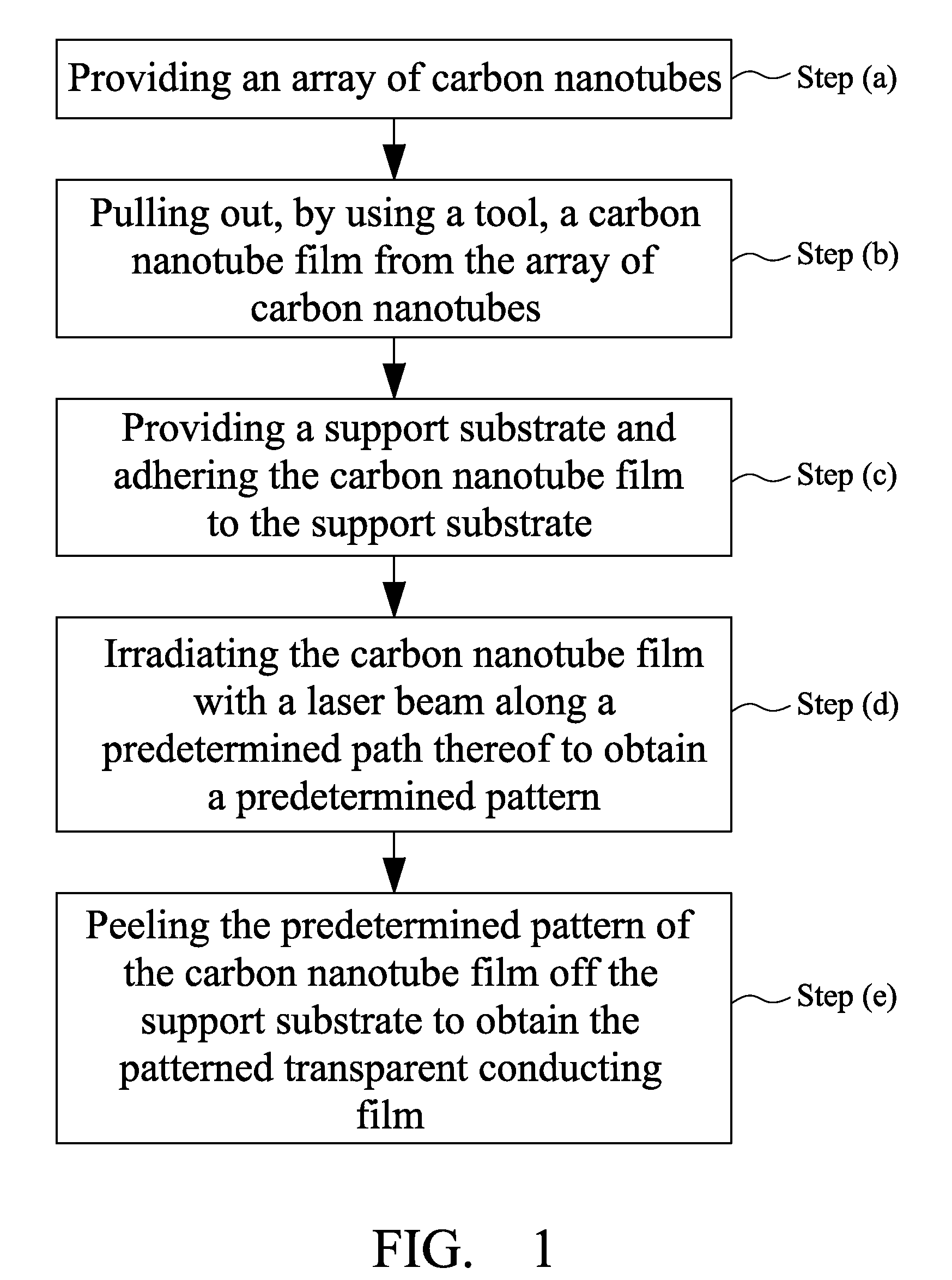
[0014]Referring to FIG. 1, a method for making a transparent conductive film, according to the present embodiment, comprises the steps of: (a) providing an array of carbon nanotubes (including super-aligned arrays); (b) extracting a portion of the carbon nanotubes from the array of carbon nanotubes to form a carbon nanotube film; (c) providing a support substrate and adhering the carbon nanotube film to the support substrate; (d) irradiating the carbon nanotube film with a laser beam along a predetermined path on the nanotube film thereby to cut a predetermined pattern within the path, wherein the laser beam has a power density of 10000-100000 watts per square meter and a moving speed of 800-1500 mm / s; (e) removing the predetermined pattern of the carbon nanotube film from the support substrate to obtain the required transparent co...


PUM


Abstract

A method of making a transparent conductive film includes the steps of: providing a carbon nanotube array. At least one carbon nanotube film extracted from the carbon nanotube array. The carbon nanotube films are stacked on the substrate to form a carbon nanotube film structure. The carbon nanotube film structure is irradiated by a laser beam along a predetermined path to obtain a predetermined pattern. The predetermined pattern is separated from the other portion of the carbon nanotube film, thereby forming the transparent conductive film from the predetermined pattern of the carbon nanotube film.

Description

BACKGROUND[0001]1. Field of the Disclosure[0002]The disclosure relates to a method of making a conductive film, and particularly to a method of making a transparent conductive film.[0003]2. Description of Related Art[0004]A transparent conductive film has a characteristic of high electrical conductivity, low electrical resistance and good light penetrability. Since Baedeker's first report of transparent conductive film in 1907, in which the transparent conductive film is prepared by thermal oxidation of sputtered Cd film, attention is paid to the research and development of the transparent conductive film. Nowadays, the transparent conductive film has been widely used in liquid crystal display (LCD), touch panel, electrochromic devices and airplane windows.[0005]The conventional methods for forming the transparent conductive film include vacuum evaporation method and magnetron sputtering method. The drawbacks of these methods include complicated equipment, high cost and being not su...

Claims


Application Information

Patent Timeline
IPC IPC(8): A61N5/00
CPCH01B1/04Y10S977/90Y10S977/89Y10S977/901Y10S977/789Y10S977/788Y10S977/742Y10S977/842
Inventor CHEN, ZHUOJIANG, KAI-LIFAN, SHOU-SHAN
Owner TSINGHUA UNIV
Learn More