Particle Counter with Laser Diode

a laser diode and particle counter technology, applied in the field of light scattering particle counters, can solve the problems of in-situ systems taking more time to achieve a statistically significant determination of fluid cleanliness, and their operation principles are very different from the principles used in particle counters

Inactive Publication Date: 2009-10-29
PARTICLE MEASURING SYST
View PDF21 Cites 40 Cited by
  • Summary
  • Abstract
  • Description
  • Claims
  • Application Information

AI Technical Summary

Benefits of technology

[0012]The present invention advances the art and helps to overcome the aforementioned problems by providing a liquid particle counter utilizing a laser diode which provides a high power beam in a low noise system for rapid detection and measurement of small particles. Preferably, the beam is symmetrically collimated and has a power of a watt or more. Preferably the beam is passed through apertures that remove most of the diffracted and stray light inherent in high power symetrized laser beams. One aspect of the invention provides a glass or crystalline aperture element in the sample chamber wall which blocks diffracted and stray light without being damaged by the high power laser beam.

Problems solved by technology

These latter systems rely on collecting scattered light from thousands, millions, and even billions of particles; therefore, their principles of operation are very different from the principles used in particle counters.
Physical constraints require tradeoffs between the above goals.
This generally results in light scattered from the physical constraining objects, such as a nozzle or flow tube, also being collected, which light creates noise in the output.
As a result of measuring only a selected fraction of fluid flow, however, in-situ systems take more time to achieve a statistically significant determination of the fluid cleanliness level or fluid quality.
When measuring particle contamination levels in a clean room environment, this extended measurement time generally incurs the risk that an unacceptably high level of airborne or liquid particle concentration could go undetected for substantial time periods, thereby allowing a large number of manufactured parts to be produced under unacceptably “dirty” conditions.
This situation can lead to substantial economic loss owing to the waste of time and production materials in the affected facility.
However, as indicated above, volumetric measurement systems generally experience more noise than do in-situ systems because the efforts expended to control the location and flow characteristics of the fluid being analyzed generally perturbs the characteristics being measured to a greater extent than does in-situ measurement.
However diode particle counters have an inherent limitation for use in particle counters that limits their power.
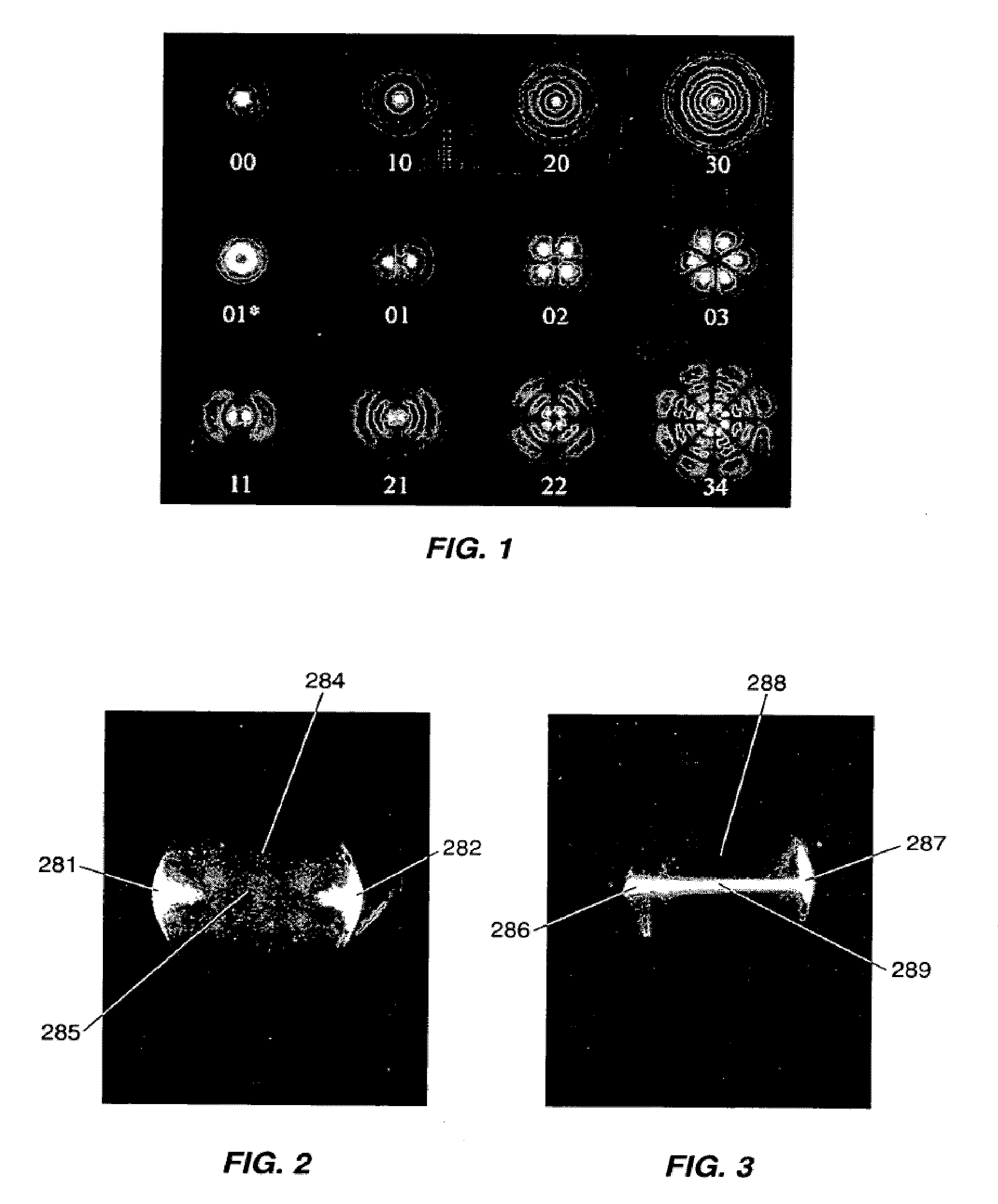
However, in particle counters, these modes scatter and reflect from the parts of the system constraining the fluid flow and create noise which interferes with the detection of particles and places a lower limit on the size of the particles that can be detected.
Thus, particle counters that use laser diodes generally limit the mode to the TEM00 mode, which however limits the amount of power of the diode, because, as indicted above, higher power requires a larger radiating surface, which inherently creates non TEM00 modes.
The problems with using high power diodes are particularly acute in particle counters that detect single particles in liquids, referred to herein as “liquid particle counters”.
If lasers having a power of one watt or greater are used in a liquid particle counter, the heat from the combination of the non TEM00 mode scattering and the diffraction from a bubble will damage the flow cell.
Thus, all known commercial liquid particle counters that utilize laser diodes to detect and measure single particles in fluids have, up until now, been limited to single mode systems, typically the TEM00 mode, and thus limited to less than 1 watt in power.

Method used


Image

  • Particle Counter with Laser Diode
  • Particle Counter with Laser Diode
  • Particle Counter with Laser Diode

Examples


Embodiment Construction

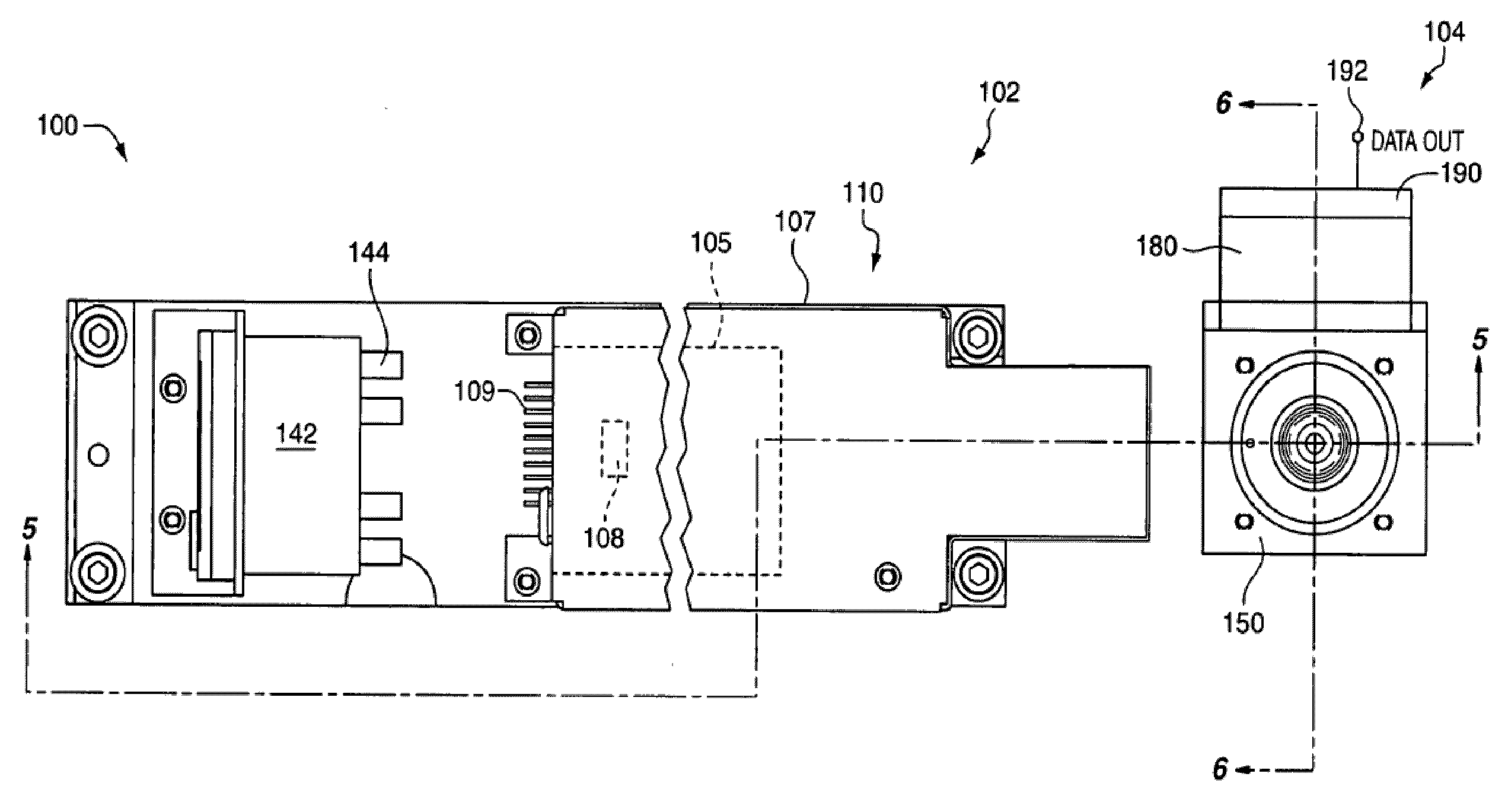
[0034]In this disclosure, the term light is not limited to visible radiation but is used in a broad sense meaning any electromagnetic radiation. Stray light includes any light that is not wanted; i.e., light that is not light scattered from particles but which can get into the collection optics. Multiply reflected light is a significant source of stray light in a particle counter. That is, light that is reflected once, scattered from a scattering source, or diffracted by a lens or aperture can usually be blocked out by other apertures or absorbing black walls because the source of the unwanted light is. However, multiple reflections make it difficult to determine the direction of the light, and thus often cannot be apertured or otherwise blocked out. The terms in-situ and volumetric are used as described in the Background of the Invention above. It is also noted that this disclosure is limited to fluid particle counters, which is a term of art. There are particle counters that detec...


PUM

PropertyMeasurementUnit
poweraaaaaaaaaa
poweraaaaaaaaaa
diameteraaaaaaaaaa

Abstract

A liquid particle counter for optically detecting an unconstrained particle suspended in a flowing liquid includes a sample chamber having a liquid inlet and a liquid outlet; a laser diode module producing a symmetrically collimated laser beam; a beam shaping optical system directing the laser beam at the sample chamber; and an optical detector located to detect light scattered by the particle in the sample chamber, the detector producing an electric signal characteristic of a parameter of the particle. The laser beam has an energy of a watt or more and passed through an aperture in a black glass aperture element in the sample chamber. The black glass aperture element removes diffracted and stray light from the beam without damage to the sample chamber.

Description

CROSS REFERENCE TO RELATED APPLICATION[0001]This application is a continuation of U.S. application Ser. No. 10 / 923,339 filed on Aug. 20, 2004, which is a continuation in part of U.S. application Ser. No. 10 / 228,577, filed on Aug. 27, 2002, now U.S. Pat. No. 6,859,277, all of which are hereby incorporated by reference in their entireties.FIELD OF THE INVENTION[0002]The invention in general relates to systems which utilize light scattering principles to detect and count undesirable single particles in fluids, referred to in the art as light scattering particle counters, and more particular to such a particle counter that utilizes a laser diode light source.STATEMENT OF THE PROBLEM[0003]Particle counters are used to detect and measure the size of individual particles suspended in a fluid. Each particle that is detected is counted, and an indication of the number of particle counts within a channel, with each channel corresponding to a particular size range, is provided. For particle co...

Claims


Application Information

Patent Timeline
Patent Type & Authority Applications(United States)
IPC IPC(8): G01N21/49B01J19/12
CPCG01N15/0205G01N21/05G01N21/51G01N2021/0346G01N2201/0633G01N2201/0642G01N2201/0612
Inventor WAGNER, GREGG A.
Owner PARTICLE MEASURING SYST
Why Eureka
Try Eureka