
Anti-dazzling optical laminate

Active Publication Date: 2009-10-29
DAI NIPPON PRINTING CO LTD
View PDF1 Cites 39 Cited by
  • Summary
  • Abstract
  • Description
  • Claims
  • Application Information

AI Technical Summary

Benefits of technology

[0014]At the time of the present invention, the present inventors have found that it is possible to provide an optical laminate which, while imparting anti-dazzling properties, can realize the so-called glossy black feeling (wet glossy black color) by improving the anti-glare property and the contrast, especially improving black color reproduction. The present invention has been made based on such finding.
[0015]Accordingly, the present invention provides an optical laminate which can realize an anti-dazzling function, an excellent anti-glare property, and excellent black color reproduction and, at the same time, can realize image display having a high level of visibility.
[0022]The optical laminate according to the present invention can realize excellent anti-dazzling properties and black color reproduction having glossy black feeling, can realize a high level of sharpness and excellent contrast, anti-glare property, and letter blurring preventive property, and can be used in various displays. In particular, the optical laminate according to the present invention can provide an optical laminate which is significantly improved in black color gradation rendering (glossy black color reproduction) in a light room, which could not have been realized by the conventional anti-dazzling laminate without difficulties. More specifically, it is possible to provide an optical laminate which, in an image in movie display, can render gradation substantially comparable with a conventional display provided with only a laminate comprising a flat clear hard coat layer free from any concavoconvex shape, or comprising a clear hard coat layer and an antireflection layer and, at the same time, can realize a good sharpness of the contour of letters and can prevent scintillation. In particular, the optical laminate according to the present invention is advantageous in that images which are significantly improved in black color gradation rendering (glossy black color reproduction) in a light room can be provided.
[0023]In a preferred embodiment of the present invention, the anti-dazzling layer may be formed in a single layer structure. Alternatively, the anti-dazzling layer may be formed by forming a surface modifying layer on a substrate concavoconvex layer having a concavoconvex shape. Further, another optical function layer may be stacked on the anti-dazzling layer having a single layer structure or the surface modifying layer. In the anti-dazzling optical laminate having the above construction, a fine concavoconvex shape may be sealed in such a state that a concavoconvex shape mainly having a smooth and gentle waviness is present whereby desired anti-dazzling properties can be exhibited. As a result, when the surface modifying layer is formed, the anti-dazzling optical laminate can impart various functions such as antistatic properties, hardness regulation, refractive index regulation, and contamination prevention to the optical laminate. In the preferred embodiment of the present invention, the expression “a concavoconvex shape having a smooth and gentle waviness” as used herein means that, unlike the concavoconvex shape in the prior art which always draws a wavy sine curve, the convex part has a large and smooth shape and a part between the convexes has a shape very close to “a flat shape” rather than the concave shape. In a preferred embodiment of the present invention, the presence of the concavoconvex shape can realize better anti-dazzling properties and a high level of black color reproduction having a glossy black feeling.
[0024]The present invention will be described in conjunction with FIG. 4 for easily understanding the details of the preferred concavoconvex shape. FIG. 4 shows optical microphotographs (reflection photographing; magnification: 20 times; upper diagram) of a preferred concavoconvex shape (left) In the present invention and a conventional concavoconvex shape (right), and a typical diagram of a sectional concavoconvex shape (lower diagram). From the optical photomicrographs shown in FIG. 4, it is understood that, unlike the conventional concavoconvex shape (right), the concavoconvex shape (left) of the present invention has a gentle flat part. Further, according to the typical diagram of a sectional concavoconvex shape in FIG. 4, the angle of the bottom (flat part) in the concave part in the present invention to the tangential line to the profile peak of the convex part is very small. On the other hand, as can be seen from the optical photomicrographs and the typical diagram of sectional concavoconvex shape in FIG. 4, unlike the present invention, the conventional concavoconvex shape (right) is substantially free from any flat part, and the concavoconvex shape continues smoothly. In this shape, very excellent anti-dazzling properties can be realized, but on the other hand, since all the concavoconvexes are in a curve form, light is diffused in every part resulting in unsatisfactory glossy black feeling.

Problems solved by technology

Accordingly, a concavoconvex shape having a broad and large curve has been regarded as unsuitable for meeting a demand for higher definition in the anti-dazzling laminate having the above construction and thus have not been adopted.
Regarding this technique, however, it has often been pointed out that external light is reflected from the display surface resulting in such a phenomenon that, for example, the image display surface is seen white (whitening), or lowered contrast.
When the light transmitted through the backside of backlight within a display is transmitted through the concavoconvex shape face of the anti-dazzling laminate formed on the outermost surface of the panel, however, the concavoconvex shape functions as Fine lenses which disturb the displayed pixels and the like, that is, “glare,” is likely to occur.
This unfavorable phenomenon makes it difficult to attain the effect of the anti-dazzling laminate per se.
On the other hand, in the anti-dazzling laminate, the method for preventing the “glare” in high-definition panels has been regarded as a main cause of an unfavorable phenomenon, for example, a deterioration in contrast such as clouding caused by surface whitening, internal scattering effect or the like.
That is, it has been regarded that ‘glare prevention’ and “contrast improvement” are in the relationship of tradeoff, and simultaneously meeting both the requirements is difficult.
In the above methods, for example, black color reproduction including glossy black feeling (wet glossy black color) in on-screen display, contrast and the like have sometimes been poor.
That is, gradation rendering of black color in a light room, particularly a black color gradation difference in low gradation, cannot be regarded without difficulties resulting in lowered sensitivity.
In particular, an anti-dazzling laminate having better anti-glare properties has a significantly lowered level of visibility.
This method, however, has many problems regarding production, for example, difficulties of film thickness regulation of the coating film, and many of necessary materials are expensive.
Accordingly, this method is unsuitable for mass production at low cost.
Although the reflectance can be minimized, in some environment where a display is viewed, image reflection cannot be satisfactorily prevented.
In this case, however, interference color occurs, and, in some cases, white and black of the display screen are changed to a reddish or bluish color.
On the other hand, when the reflectance is not very low, since the outermost surface is smooth, effectively preventing the image reflection is very difficult.
According to studies by the present inventors, however, any anti-dazzling laminate, which can prevent glare feeling and can satisfactorily reproduce glossy black feeling of images in a light room, has not been developed yet.
Further, in an antireflection film formed by coating a composition comprising a binder and an inorganic filler, the brightness and resolution of transmitted images are deteriorated.

Method used


Image

  • Anti-dazzling optical laminate
  • Anti-dazzling optical laminate
  • Anti-dazzling optical laminate

Examples


example 1

Formation of Substrate Concavoconvex Layer

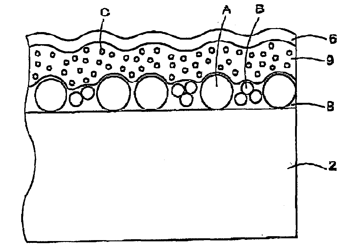
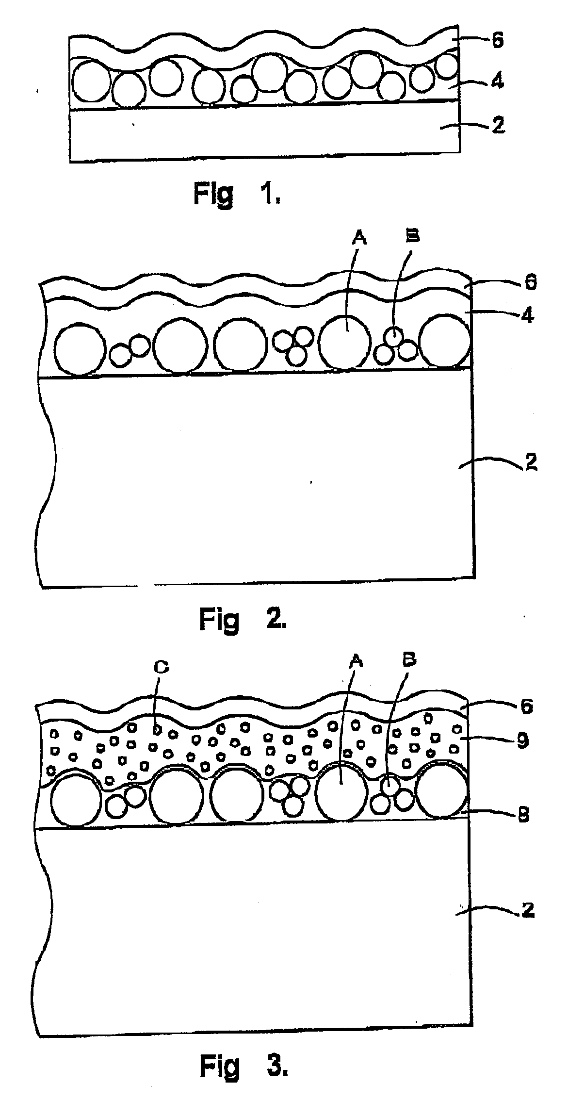
[0327]An 80 μm-thick triacetylcellulose film (TD80U, manufactured by Fuji Photo Film Co., Ltd.) was provided as a transparent base material. Composition 1 for a substrate concavoconvex layer was coated onto the transparent base material with a wire-wound rod for coating (Mayer's bar) #10, and the coated transparent base material was heat dried in an oven of 70° C. for one min to evaporate the solvent component. Thereafter, under nitrogen purge (oxygen concentration: not more than 200 ppm), ultraviolet light was applied at an exposure of 14 mJ to cure the coating film and thus to form a substrate concavoconvex layer. In this case, the development of an internal diffusion effect and more effective prevention of scintillation could be realized by using fine particles having a maximum refractive index difference of 0.17 from that of the binder resin in the substrate concavoconvex layer.

[0328]Formation of Surface Modifying Layer

[0329]Composition ...

example 2

Formation of Substrate Concavoconvex Layer

[0330]An 80 μm-thick triacetylcellulose film (TD80U, manufactured by Fuji Photo Film Co., Ltd.) was provided as a transparent base material. Composition 2 for a substrate concavoconvex layer was coated onto the transparent base material with a wire-wound rod for coating (Mayer's bar) #10, and the coated transparent base material was heat dried in an oven of 70° C. for one min to evaporate the solvent component. Thereafter, ultraviolet light was applied at an exposure of 30 mJ to cure the coating film and thus to form a substrate concavoconvex layer. In this case, the development of an internal diffusion effect and more effective prevention of scintillation could be realized by using fine particles having a maximum refractive index difference of 0.09 from that of the binder resin in the substrate concavoconvex layer.

[0331]Formation of Surface Modifying Layer

[0332]Composition 1 for a surface modifying layer was further coated onto the substrat...

example 3

Formation of Substrate Concavoconvex Layer

[0333]An 80 μm-thick triacetylcellulose film (TD80U, manufactured by Fuji Photo Film Co., Ltd.) was provided as a transparent base material. Composition 2 for a substrate concavoconvex layer was coated onto the transparent base material with a wire-wound rod for coating (Mayer's bar) #10, and the coated transparent base material was heat dried in an oven of 70° C. for one min to evaporate the solvent component. Thereafter, ultraviolet light was applied at an exposure of 30 mJ to cure the coating film and thus to form a substrate concavoconvex layer. In this case, the development of an internal diffusion effect and more effective prevention of scintillation could be realized by using fine particles having a maximum refractive index difference of 0.09 from that of the binder resin in the substrate concavoconvex layer.

[0334]Formation of Surface Modifying Layer

[0335]Composition 3 for a surface modifying layer was further coated onto the substrat...


PUM

PropertyMeasurementUnit
Fractionaaaaaaaaaa
Fractionaaaaaaaaaa
Angleaaaaaaaaaa

Abstract

Disclosed is an anti-dazzling laminate which has anti-dazzling properties and can realize excellent glare preventive properties and black color reproducibility (gradation rendering of black color at low brightness). The anti-dazzling laminate is an optical laminate comprises a light transparent base material and an anti-dazzling layer provided on the light transparent base material, wherein the outermost surface of the anti-dazzling layer has a concavoconvex shape, and the optical laminate satisfies the following requirements: Ha is more than 0% and less than 90%, Hi is more than 0% and less than 90%, and Hi / Ha is not less than 0.8 and less than 1.0, wherein Ha represents the whole haze value of the optical laminate; and Hi represents the internal haze value of the optical laminate.

Description

RELATED APPLICATION[0001]This application is based upon and claims the benefit of priority from the prior Japanese Patent Application No. 221193 / 2006 under the Paris Convention, and, thus, the entire contents of the basic application are incorporated herein by reference.TECHNICAL FIELD[0002]The present invention provides an anti-dazzling optical laminate for use in displays such as CRTs, PDPs, and liquid crystal panels.BACKGROUND ART[0003]The prevention of lowered contrast and lowered visibility caused by external light reflection or image reflection is required of image display devices, for example, cathode-ray tube display devices (CRTs), plasma displays (PDPs), electroluminescent displays (ELDs), or liquid crystal displays (LCDs). Accordingly, it is common practice to provide an antireflection laminate on the outermost surface of an image display device from the viewpoint of reducing image reflection or reflectance using the principle of light scattering or the principle of optic...

Claims


Application Information

Patent Timeline
IPC IPC(8): G02B1/11
CPCG02B5/0226G02B5/0242G02B5/0278Y10T428/24355G02F1/133504Y10T428/24364G02F1/133502G02B1/11G02B5/02
Inventor FURUI, GENIWATA, YUKIMITSUNISHIMURA, YOSHIHIROKODAMA, TAKASHI
Owner DAI NIPPON PRINTING CO LTD
Learn More