

System and Method for Permanently Writing a Diffraction Grating in a Low Phonon Energy Glass Medium
a low phonon energy glass medium and permanent writing technology, applied in the field of inducing a permanent refractive index pattern, or diffraction grating, can solve the problems of weak refractive index change in fluoride glass-based waveguides, no significant refractive index change has been reported, and the effect of limit grating erasing thermal effects
- Summary
- Abstract
- Description
- Claims
- Application Information
AI Technical Summary
Benefits of technology
Problems solved by technology
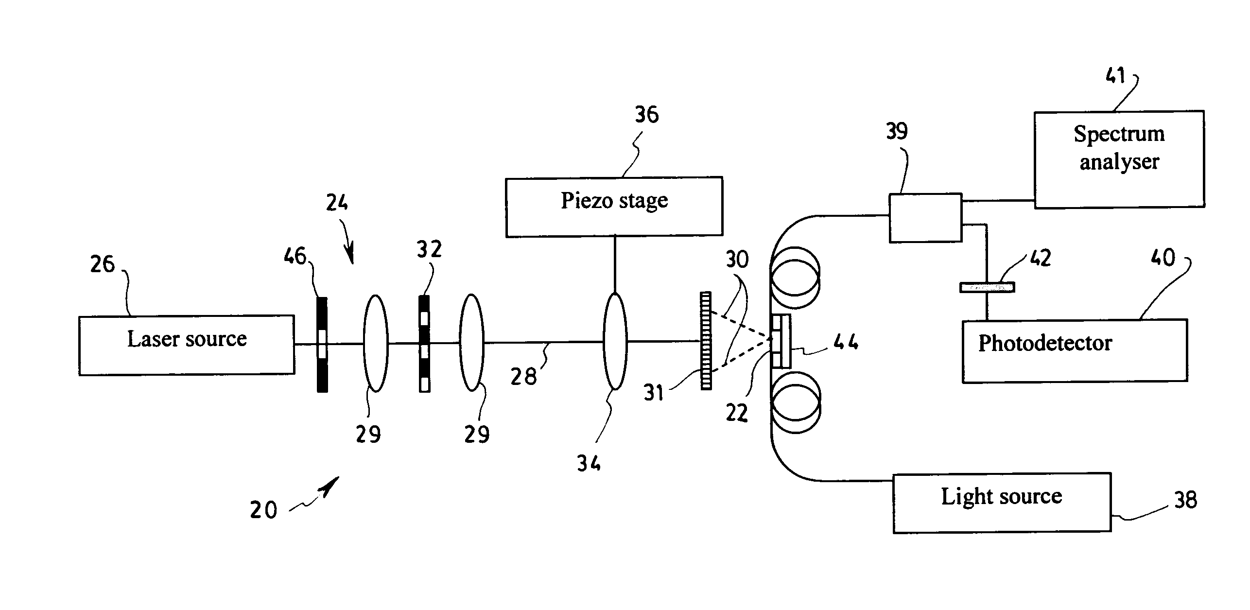
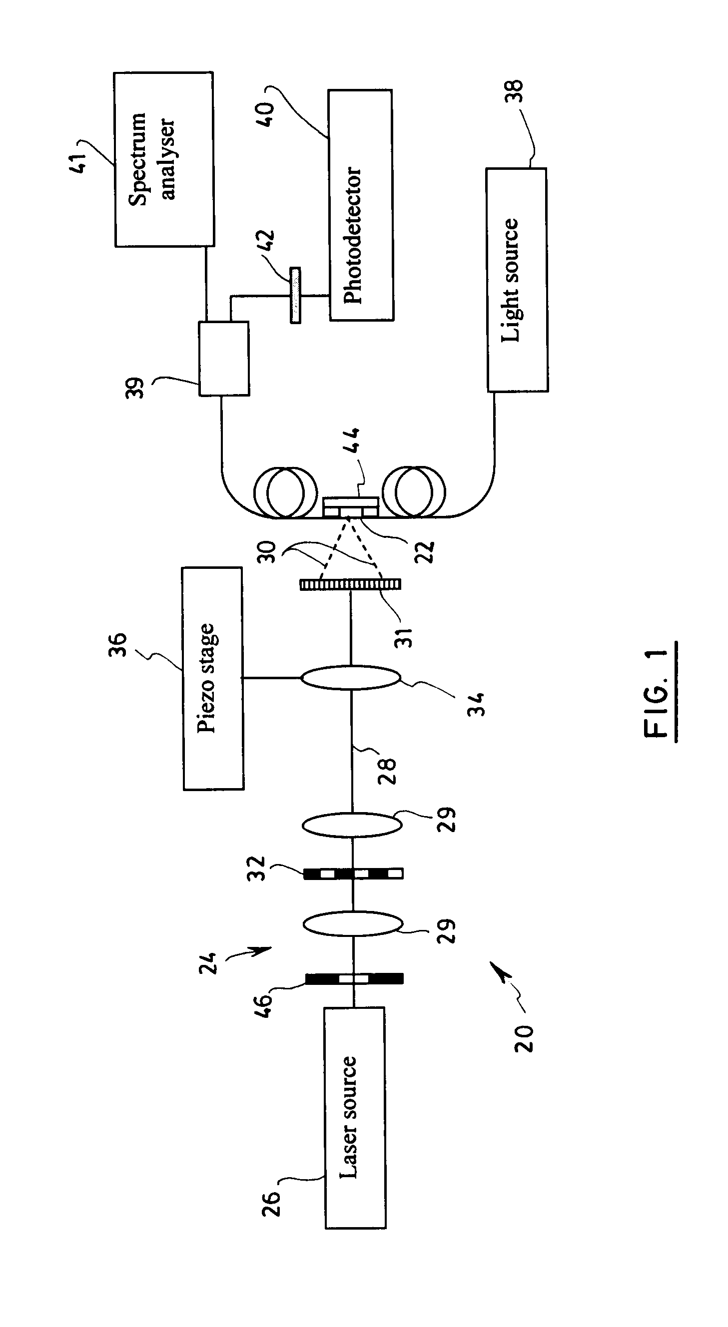
Method used
Image

Examples
example 1
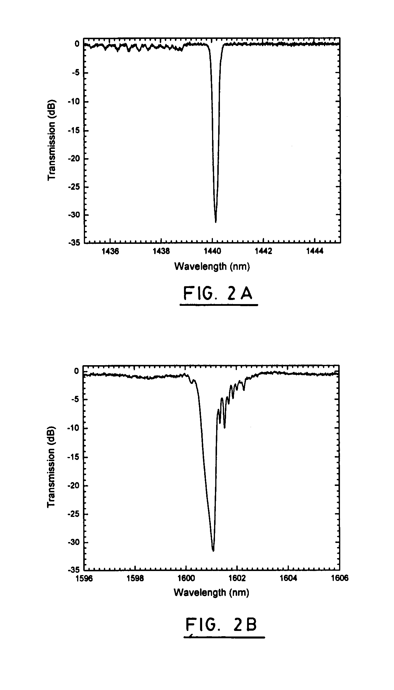
[0064]The setup described above was used to inscribe Bragg gratings in an undoped single-mode ZBLAN fiber and, for the sake of comparison, in a hydrogen-free standard single-mode silica fiber (SMF28). The transmission spectra of the Bragg gratings written according to the preferred embodiment of the method described is shown in FIG. 2A for the silica fiber and FIG. 2B for the fluoride fiber. For the silica fiber, the control of the detrimental thermal effects previously described was not applied but the reflectivity of the resulting Bragg grating is shown to grow regularly to reach a maximum reflectivity of about 99.9% after an exposure time of about 30 seconds, as shown in FIG. 3 (Silica fiber). The same experiment was done in the undoped fluoride-based fiber and the resulting temporal evolution of the peak reflectivity is shown at FIG. 3 (case 1) in which situation the peak reflectivity was found to grow in an irregular fashion and reached no more than 20% after an exposure time o...
example 2
[0065]The setup described above was also used to inscribe Bragg gratings in both an undoped single-mode ZBLAN fiber and in a 2000 ppm thulium-doped single-mode ZBLAN fiber. The exposure time of the undoped fiber was set to about 2 seconds and the uniform phase-mask pitch was 1070 nm. The transmission spectrum of the resulting Bragg grating according to the preferred embodiment of the method described is shown in FIG. 6 (a). A numerical simulation of the corresponding grating parameters indicates that the transmission dip of −17 dB at 1598.5 nm corresponds to a 4.5 mm long uniform grating of 95% reflectivity with an index modulation ΔnAC of 3.2×10⁻⁴. Out-of-band insertion losses were measured by a cutback method to be smaller than 0.3 dB. The exposure time of the thulium-doped fiber was set to about 3 seconds and the uniform phase-mask pitch was 992 nm. The transmission spectrum of the resulting Bragg grating according to the preferred embodiment of the method described is shown in F...
PUM
 Abstract
Description
Claims
Application Information